Switch Actuation Device

Inactive Publication Date: 2015-06-25
BLAKEMAN IAN
View PDF2 Cites 3 Cited by
  • Summary
  • Abstract
  • Description
  • Claims
  • Application Information

AI Technical Summary

Benefits of technology

The present invention provides a switch actuation device that overcomes the deficiencies of the prior art. It can easily attach to an existing electrical switch and can be retrofitted. The device allows for the switch to be actuated to the "on" or "off" position according to a predetermined timing sequence. The device can also cycle between the "on" or "off" position based on the same timing sequence.

Problems solved by technology

In both consumer and commercial structures, lights are often inadvertently left on when a person exits a room, which results in a drain in energy and an increase in costs.
Often, this light, fan or other appliance may be left on for a long period of time in a room where little human traffic or through-traffic is experienced after the room is vacated.
Therefore, the user must rearrange furniture and go through an often laborious task of unplugging and resetting these devices.

Method used


Image

  • Switch Actuation Device
  • Switch Actuation Device
  • Switch Actuation Device

Examples


Embodiment Construction

[0051]For purposes of the description hereinafter, the terms “upper”, “lower”, “right”, “left”, “vertical”, “horizontal”, “top”, “bottom”, “lateral”, “longitudinal” and derivatives thereof shall relate to the invention as it is oriented in the drawing figures. However, it is to be understood that the invention may assume various alternative variations and step sequences, except where expressly specified to the contrary. It is also to be understood that the specific devices and processes illustrated in the attached drawings, and described in the following specification, are simply exemplary embodiments of the invention. Hence, specific dimensions and other physical characteristics related to the embodiments disclosed herein are not to be considered as limiting.

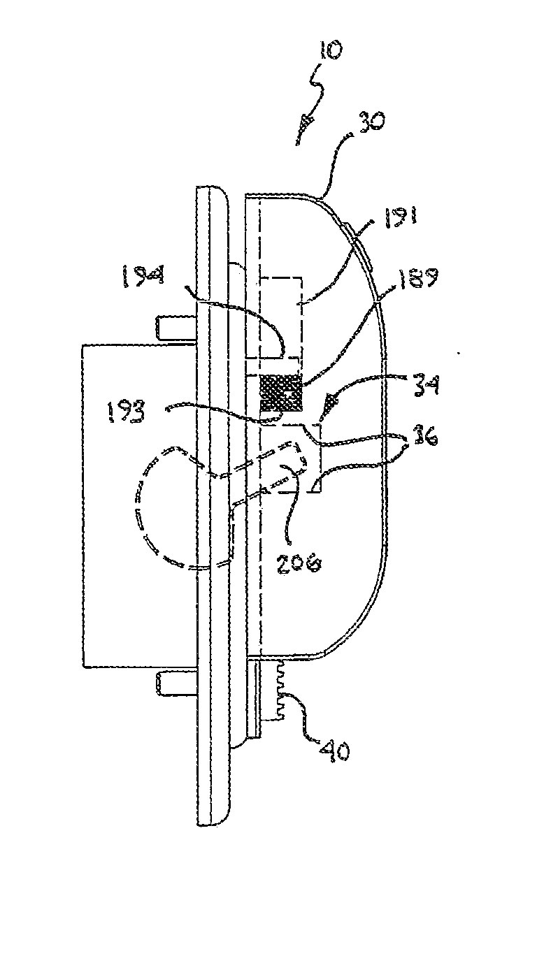
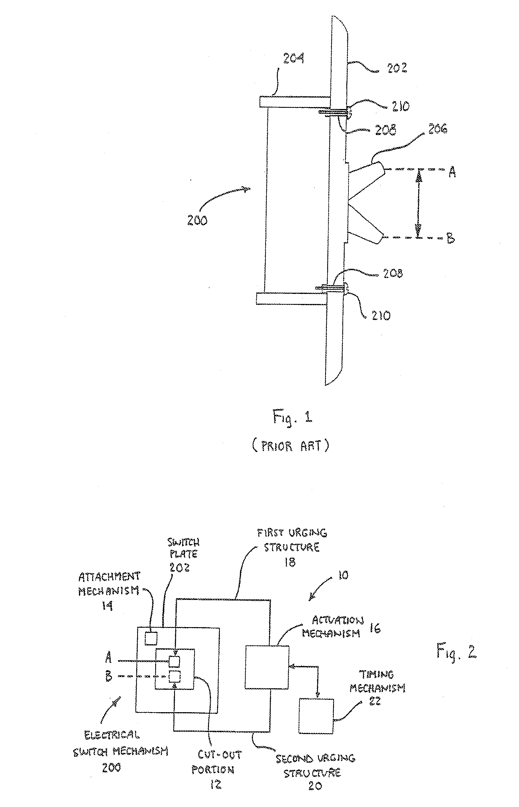
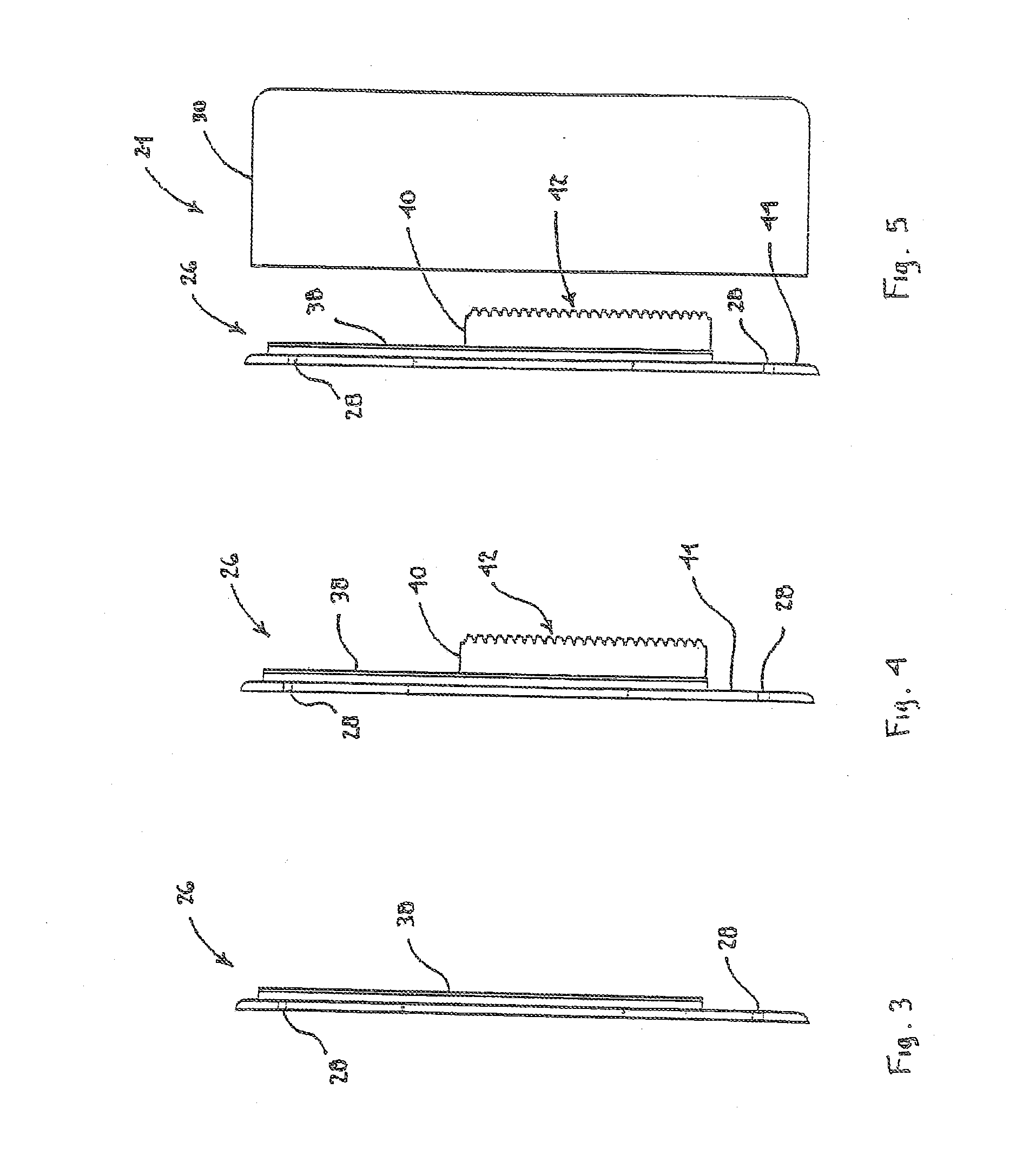
[0052]The present invention is directed to a switch actuation device 10, as illustrated in various embodiments in FIGS. 2-35. In particular, this switch actuation device 10 can be used in connection with an existing and install...


PUM


Abstract

A switch actuation device for use in connection with electrical switch mechanism having an actuatable structure. The device includes an actuation mechanism in operable communication with the actuatable structure for use in urging the actuatable structure of the electrical switch mechanism from a first position to a second position. An actuatable electrical switch arrangement is also disclosed.

Description

CROSS REFERENCE TO RELATED APPLICATIONS[0001]This application is a continuation-in-part application of application Ser. No. 13 / 933,411, filed Jul. 2, 2013, which is a continuation application of application Ser. No. 13 / 537,679, filed Jun. 29, 2012 (now U.S. Pat. No. 8,502,095), which is a divisional application of patent application Ser. No. 12 / 466,694, filed May 15, 2009 (now U.S. Pat. No. 8,232,487), which is a continuation-in-part application of patent application Ser. No. 11 / 699,272, filed Jan. 29, 2007 (now U.S. Pat. No. 7,544,906), which claims priority from U.S. Provisional Patent Application No. 60 / 763,501, filed Jan. 31, 2006, all of which are incorporated herein by reference in their entirety.BACKGROUND OF THE INVENTION[0002]1. Field of the Invention[0003]The present invention relates to mechanisms and devices that can be used in conjunction with electrical switch mechanisms, such as a light switch or similar power switch and, particularly to a switch actuation device that...

Claims


Application Information

Patent Timeline
IPC IPC(8): H01H7/12
CPCH01H7/12G04F3/06H01H43/00H01H21/52G04C23/04G04C23/14
Inventor BLAKEMAN, IAN
Owner BLAKEMAN IAN
Why Eureka
Try Eureka