
Eureka
For R&D, Eureka makes reading and utilizing patents & technical documents easy.
Eureka AIR
Designed for self-driven R&D workflows. Generate viable solutions, solve complex R&D challenges, empower your innovation with AI.

Eureka Materials
Designed for material experts only. Revolutionize your material R&D, from search, analyze, to developing new materials.

TechResearch
Generate reliable direction feasibility study reports for your R&D in just a few steps.

TechSeek
Discover and master advanced knowledge NOW. Basics, ideas, possibilities, all at once.

TechMind
As an expert in R&D Theories, TechMind can generates customized viable solutions instantly.

TechRisk
Analyze your overall solution with one click, know your potential R&D risks in advance.

TechMonitor
Get weekly tech updates, stay abreast of the latest tech innovations and key insights.
Curtain Rod Return Bracket
- Summary
- Abstract
- Description
- Claims
- Application Information
AI Technical Summary
Benefits of technology
Problems solved by technology
Method used
Image

Examples
first embodiment
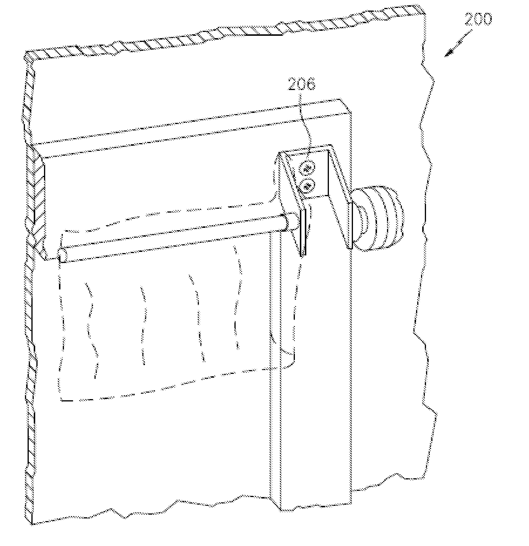
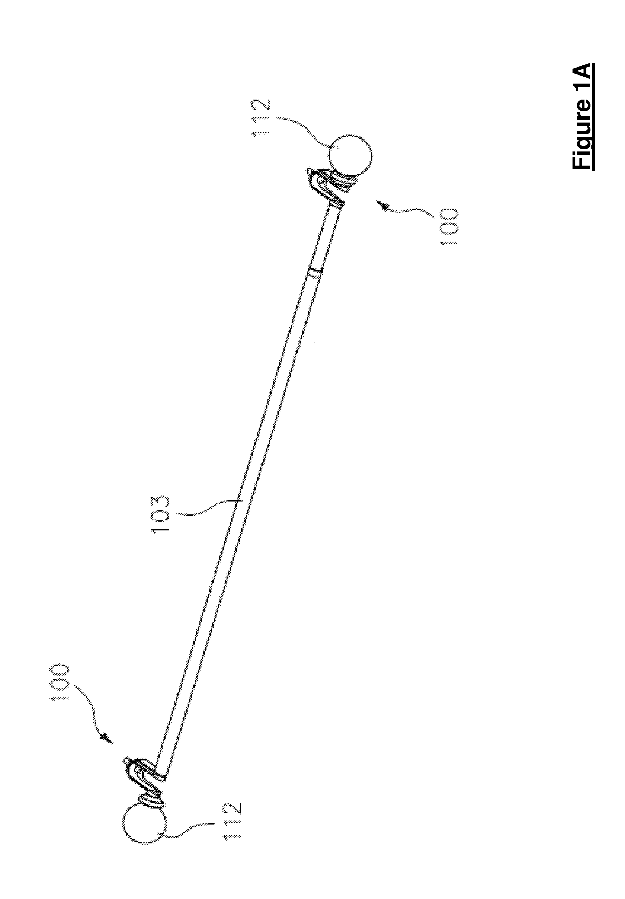
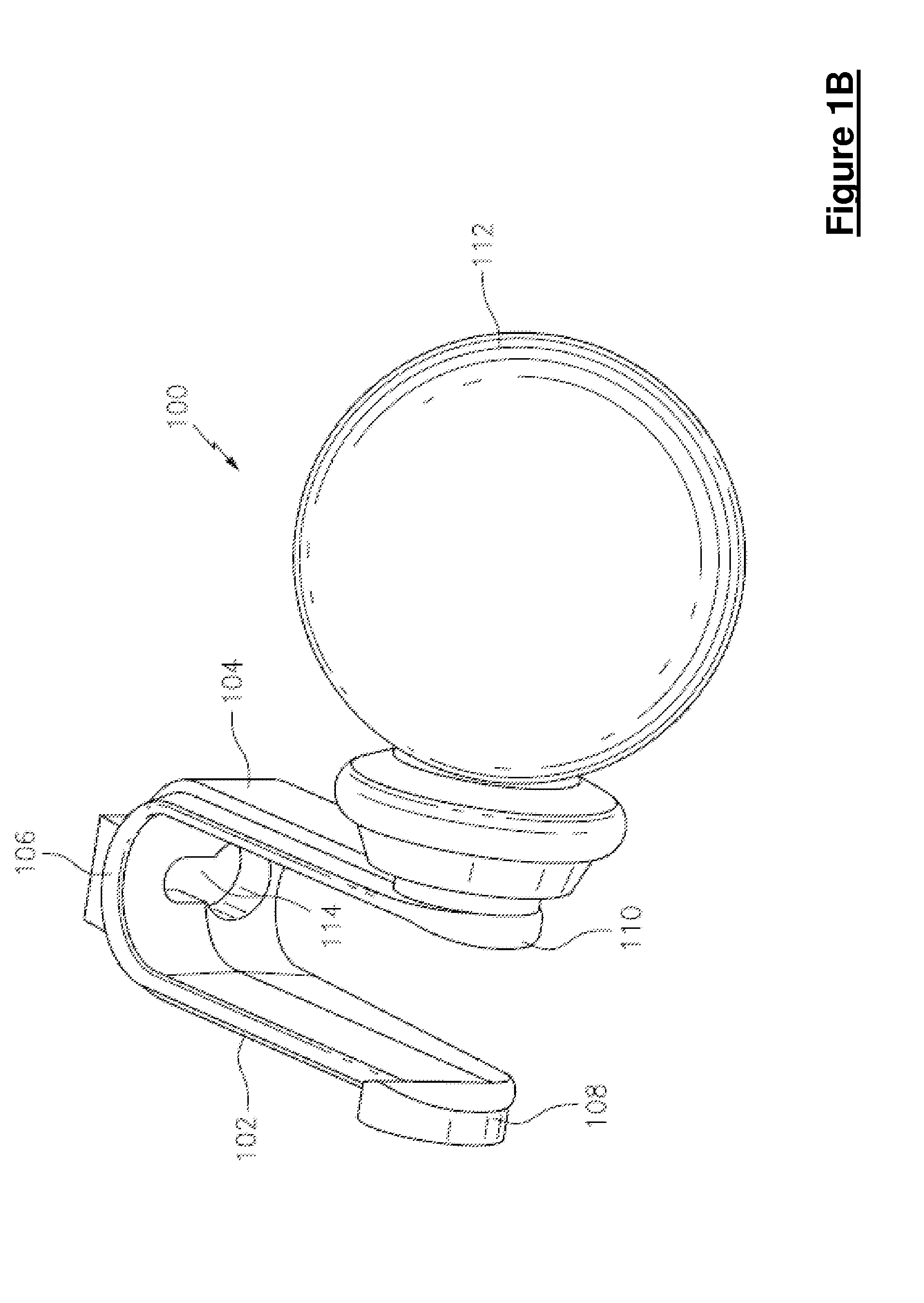
[0032]Referring to FIG. 1A, FIG. 1B, FIG. 2A, FIG. 2B and FIG. 2C, a curtain return bracket 100 is shown in accordance with the present invention. The return bracket 100 includes an inner bracket leg 102 and an outer bracket leg 104 connected via a bracket center portion 106. The bracket inner leg 102 includes a rod attachment article 108 configured to securely associate with and support a curtain rod 103. The bracket outer leg 104 includes a finial attachment article 110 configured to securely associate with and support a decorative article, such as a finial 112. It should be appreciated that the inner bracket leg 102 and the outer bracket leg 104 are arranged to be substantially perpendicular to the curtain rod 103. Additionally, the bracket center portion 106 is configured to mount to a wall proximate a window or to the trim / moulding of a window. In this embodiment, the bracket center portion 106 defines a through cavity 114 by which the return bracket 100 can be securely associa...
second embodiment
[0042]Referring to FIG. 15, still yet another embodiment of the curtain return bracket 500 is shown and is configured to operate with a flat curtain rod. In this embodiment, the curtain return bracket 500 includes a first inner bracket leg 502, a second inner bracket leg 504 and an outer bracket leg 506. As with the second embodiment, the end of the flat curtain rods attach to the first inner bracket leg 502 and second inner bracket leg 504 via any other article or method suitable to the desired end purpose, such as a clip, screw, notched portion, etc.. As with the other embodiments, the curtains associated with the first and second inner bracket legs 502, 504 may slide over and cover (or the curtain rings may cover) the first and second inner bracket legs 502, 504. This blocks / limits light from entering via the side of the window.
[0043]Referring to FIG. 16, FIG. 17 and FIG. 18, still yet another embodiment a curtain rod return bracket 600 is shown and is configured to operate with ...
PUM
 Abstract
Description
Claims
Application Information
 - R&D Engineer
- R&D Manager
- IP Professional
- Industry Leading Data Capabilities
- Powerful AI technology
- Patent DNA Extraction
Browse by: Latest US Patents, China's latest patents, Technical Efficacy Thesaurus, Application Domain, Technology Topic, Popular Technical Reports.
© 2024 PatSnap. All rights reserved.Legal|Privacy policy|Modern Slavery Act Transparency Statement|Sitemap|About US| Contact US: help@patsnap.com