This helps you quickly interpret patents by identifying the three key elements:
Problems solved by technology
Method used
Benefits of technology
Benefits of technology
The present invention is a vertical pulverizing apparatus that can prevent the wear and tear of the throat vanes, which helps to prolong their lives and increase productivity.
Problems solved by technology
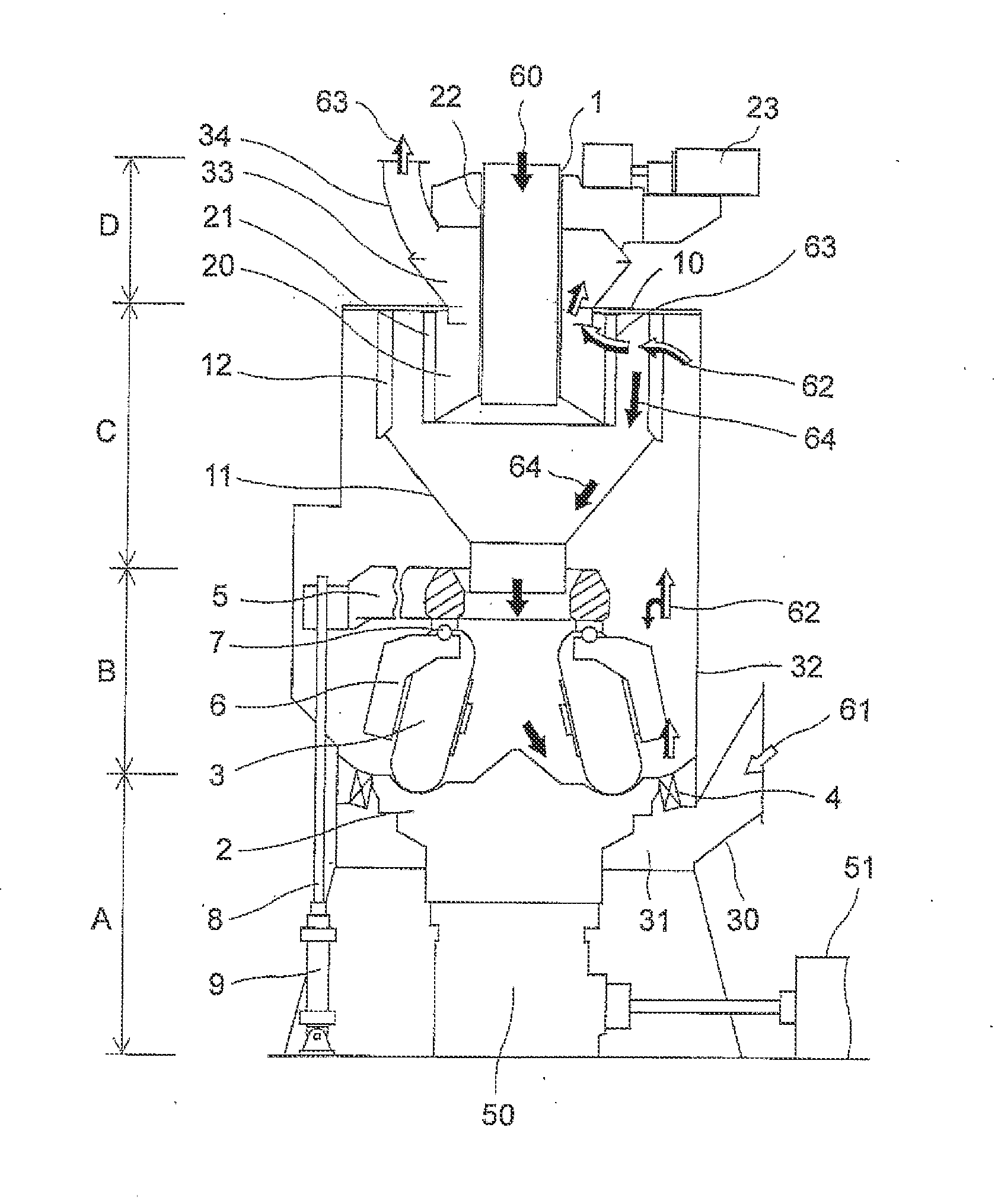
When a flammable material such as coal which is pulverized by the vertical pulverizing apparatus is deposited locally inside the vertical pulverizing apparatus, there is a danger that the deposited flammable material may be heated by the high-temperature primary air 61 supplied from the throat 4, resulting in ignition.
Method used
Image
Click on the blue label to locate the original text in one second.
Reading with bidirectional positioning of images and text.
Examples
first embodiment
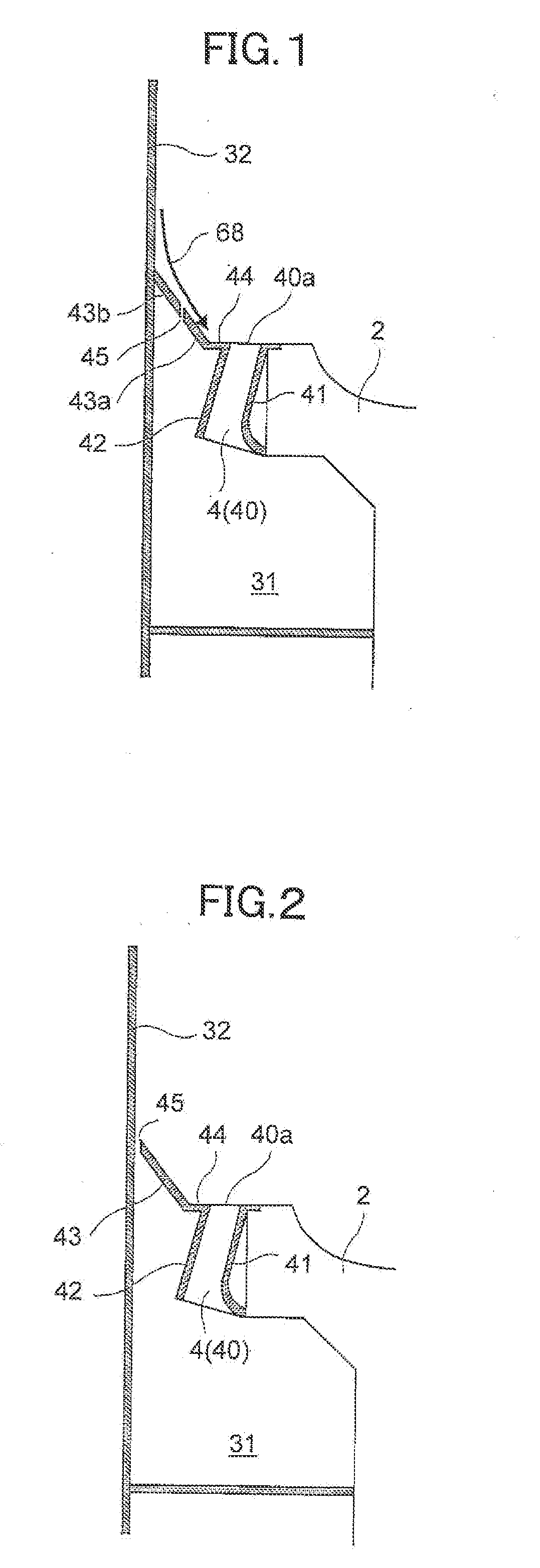
[0060]FIG. 1 is a sectional view of the vicinities of a throat portion of a vertical pulverizing apparatus according to a first embodiment of the invention. The overall configuration, functions, etc. of the vertical pulverizing apparatus are similar to those in the vertical pulverizing apparatus shown in FIG. 7, and their description will be omitted.
[0061]As shown in FIG. 1, a throat 4 is an annular flow channel surrounded by a throat inner peripheral wall 41 and a throat outer peripheral wall 42. In addition, a large number of throat vanes 40 each inclined at a desired angle α with respect to a rotation direction X of a pulverizing table 2 are placed at intervals in the circumferential direction of the throat 4 so that a turning force can be given to primary air 61 jetted from the throat 4.
[0062]In the embodiment, as shown in FIG. 1, the throat 4 is a rotary type throat which is attached to the pulverizing table 2 so as to rotate together with the pulverizing table 2.
[0063]An insid...
second embodiment
[0078]FIG. 2 is a sectional view of the vicinities of a throat portion of a vertical pulverizing apparatus according to a second embodiment of the invention.
[0079]This embodiment is different from the first embodiment shown in FIG. 1 at the point that the slope part 43 is not divided into two, but the slope part 43 consisting of one member is attached to the pulverizing table 2, and the gap 45 is formed between the slope part 43 and the housing 32. A part of particles 68 falling down can be blown upward by the primary air 61 jetted upward from the gap 45. Thus, the amount of particles 68 arriving at the too end surface 40a of each throat vane 40 can be reduced.
[0080]This embodiment has such an advantage that the slope part 43b fixed to the housing 32 can be eliminated so that the number of parts can be reduced and assembling can be made easy, as compared with the first embodiment.
third embodiment
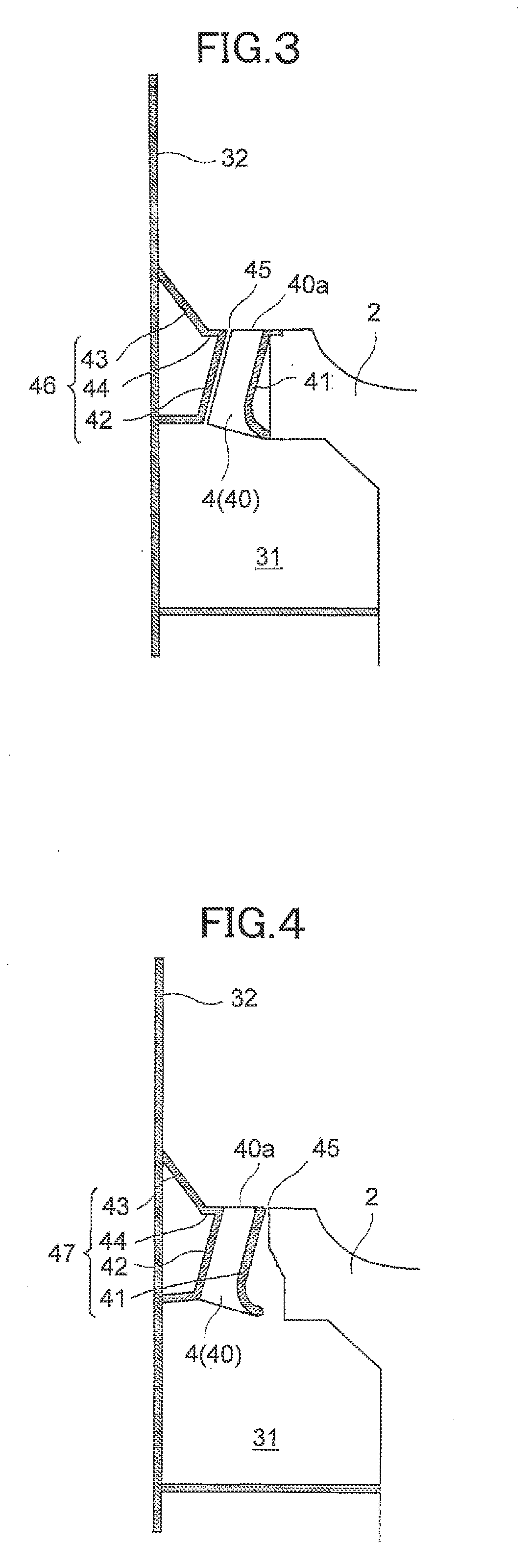
[0081]FIG. 3 is a sectional view of the vicinities of a throat portion of a vertical pulverizing apparatus according to a third embodiment of the invention.
[0082]In this embodiment, an integral structure 46 in which the slope part 43, the horizontal part 44 and the throat outer peripheral wall 42 are formed integrally is fixed to the housing 32. On the other hand, the throat inner peripheral wall 41 and the throat vanes 40 are fixed to the pulverizing table 2. Accordingly, as shown in FIG. 3, the gap 45 is formed in the annular flow channel between the throat inner peripheral wall 41 which is rotating and the throat outer peripheral wall 42 which is fixed. The gap 45 becomes a part of the annular flow channel.
[0083]According to this configuration, the flow rate of the primary air 61 flowing in the annular flow channel remains the same even when the gap 45 is widened. There fore, there is an advantage that the size of the gap 45 can be increased.
PUM
Abstract
Provided is a vertical pulverizing apparatus capable of suppressing abrasion of throat vanes (40) and elongating their abrasion resistant lives to thereby increase working efficiency. The vertical pulverizing apparatus is characterized in that: a throat (4) is provided between a housing (32) and a pulverizing table (2) and has an annular flow channel which is surrounded by a throat inner peripheral wall (41) and a throat outer peripheral wall (42) and which is partitioned by a large number of throat vanes (40); and a slope part (43a, 43b) extending diagonally downward from an inner peripheral wall surface of the housing (32) toward a top end of the throat outer peripheral wall (42) and a horizontal part (44) extending from a bottom end of the slope part (43b) continuously to the top end of the throat outer peripheral wall (42) are provided so that top end surfaces (40a) of the throat vanes (40) and a top surface of the horizontal part (44) can be set at the same height.
Description
TECHNICAL FIELD[0001]The present invention relates to a vertical pulverizing apparatus capable of pulverizing solid matter such as coal or cement by means of a pulverizing table and a pulverizer such as a pulverizing roller rolling on the pulverizing table, and adjusting the pulverized particles to a predetermined particle size distribution by means of a classification portion. Particularly, it relates to the structure of the vicinities of a throat portion.BACKGROUND ART[0002]Vertical pulverizing apparatuses are used as fuel supply units in coal fired boiler plants for thermal power generation in which pulverized coal is burned as fuel.[0003]FIG. 7 is a schematic configuration view of a background-art vertical pulverizing apparatus. As shown in FIG. 7, the vertical pulverizing apparatus is mainly constituted by a drive portion A, a pulverization portion B, a classification portion C and a distribution portion D, and the portions have a layout as illustrated.[0004]The drive portion A...
Claims
Application Information
Patent Timeline
Application Date:The date an application was filed.
Publication Date:The date a patent or application was officially published.
First Publication Date:The earliest publication date of a patent with the same application number.
Issue Date:Publication date of the patent grant document.
PCT Entry Date:The Entry date of PCT National Phase.
Estimated Expiry Date:The statutory expiry date of a patent right according to the Patent Law, and it is the longest term of protection that the patent right can achieve without the termination of the patent right due to other reasons(Term extension factor has been taken into account ).
Invalid Date:Actual expiry date is based on effective date or publication date of legal transaction data of invalid patent.

