
System and method for an outdoor lighting feature with an integrated solar panel

Inactive Publication Date: 2011-01-27
METCHEAR III CHARLES R +1
View PDF13 Cites 42 Cited by
  • Summary
  • Abstract
  • Description
  • Claims
  • Application Information

AI Technical Summary

Benefits of technology

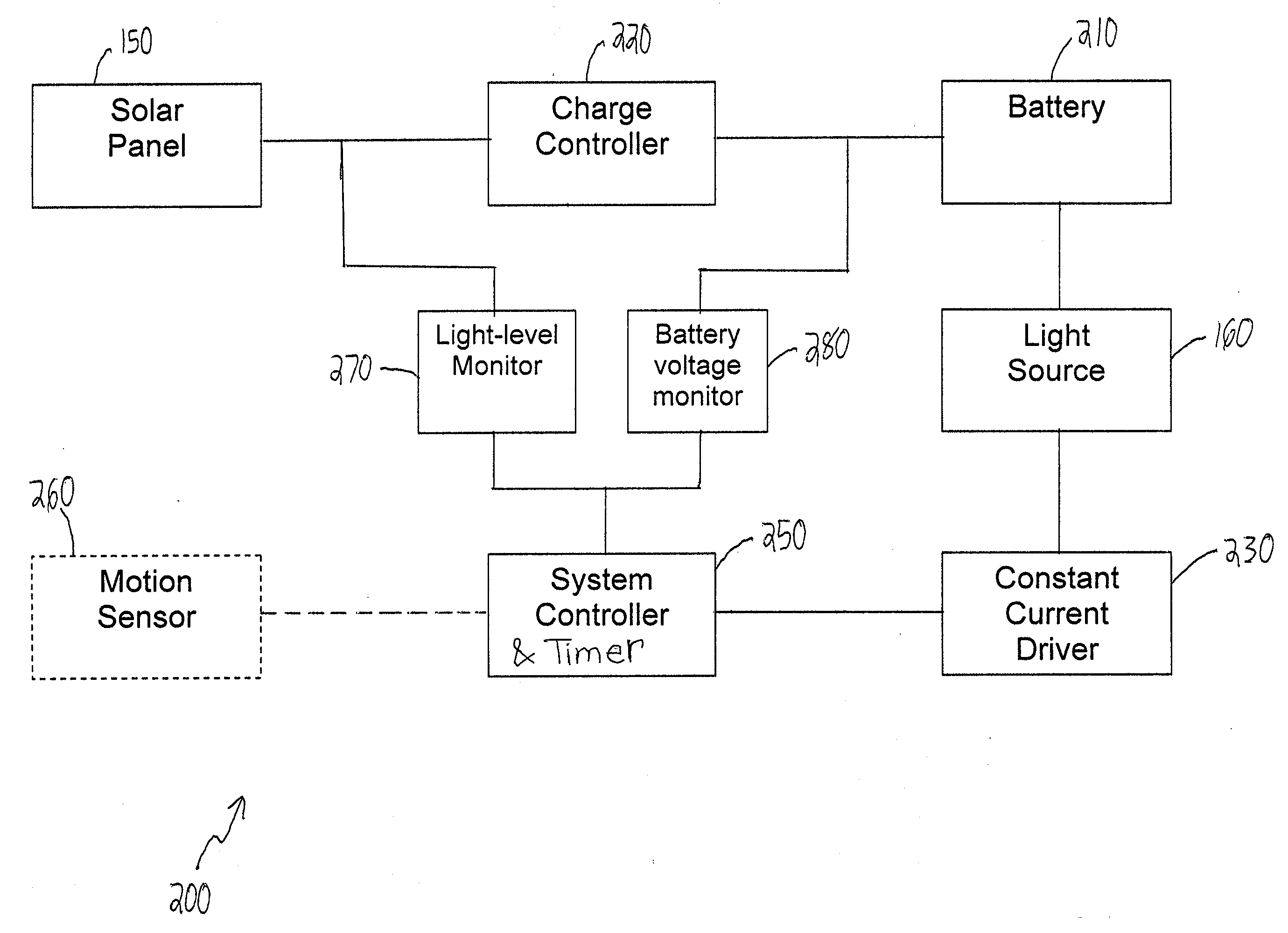
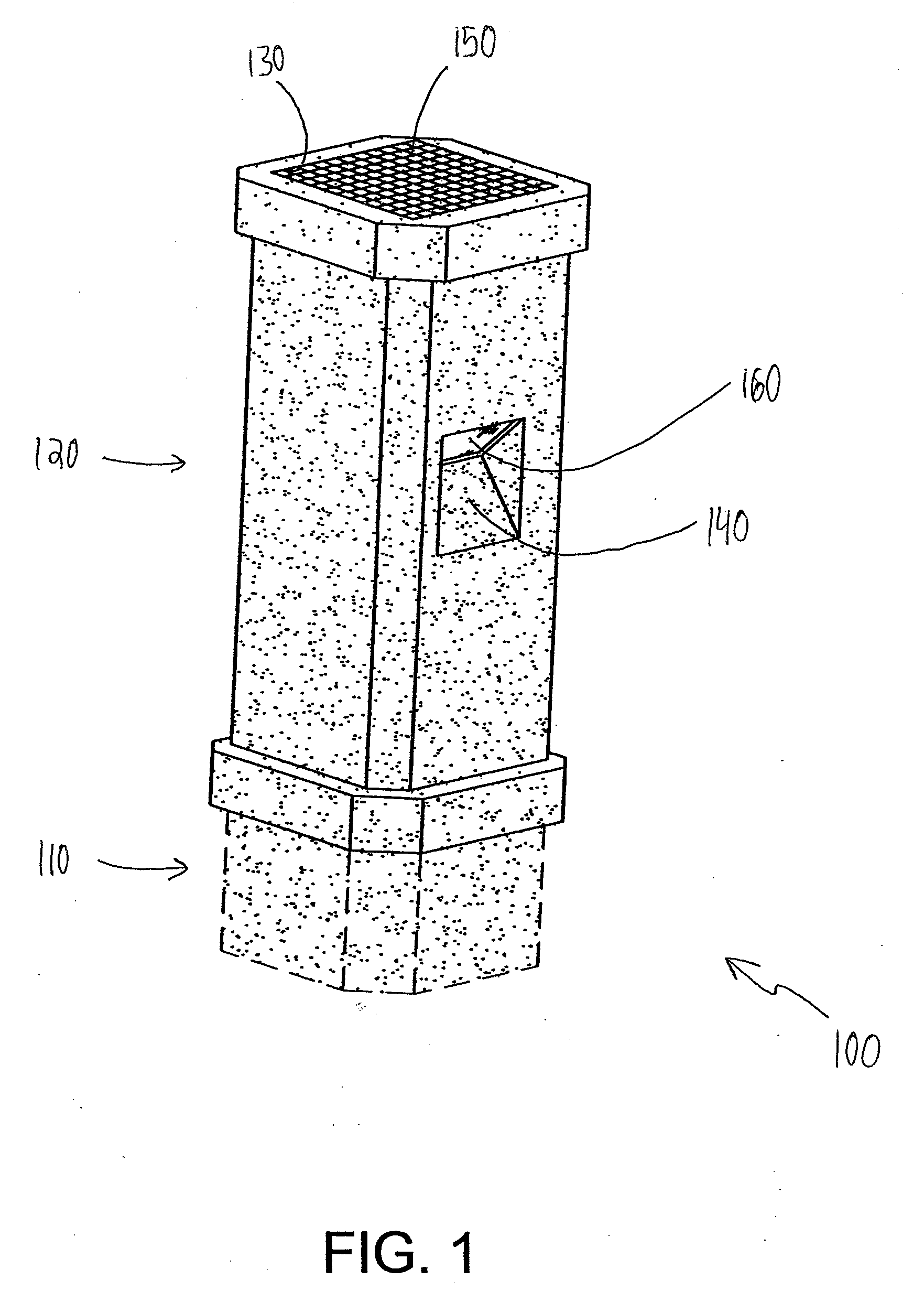
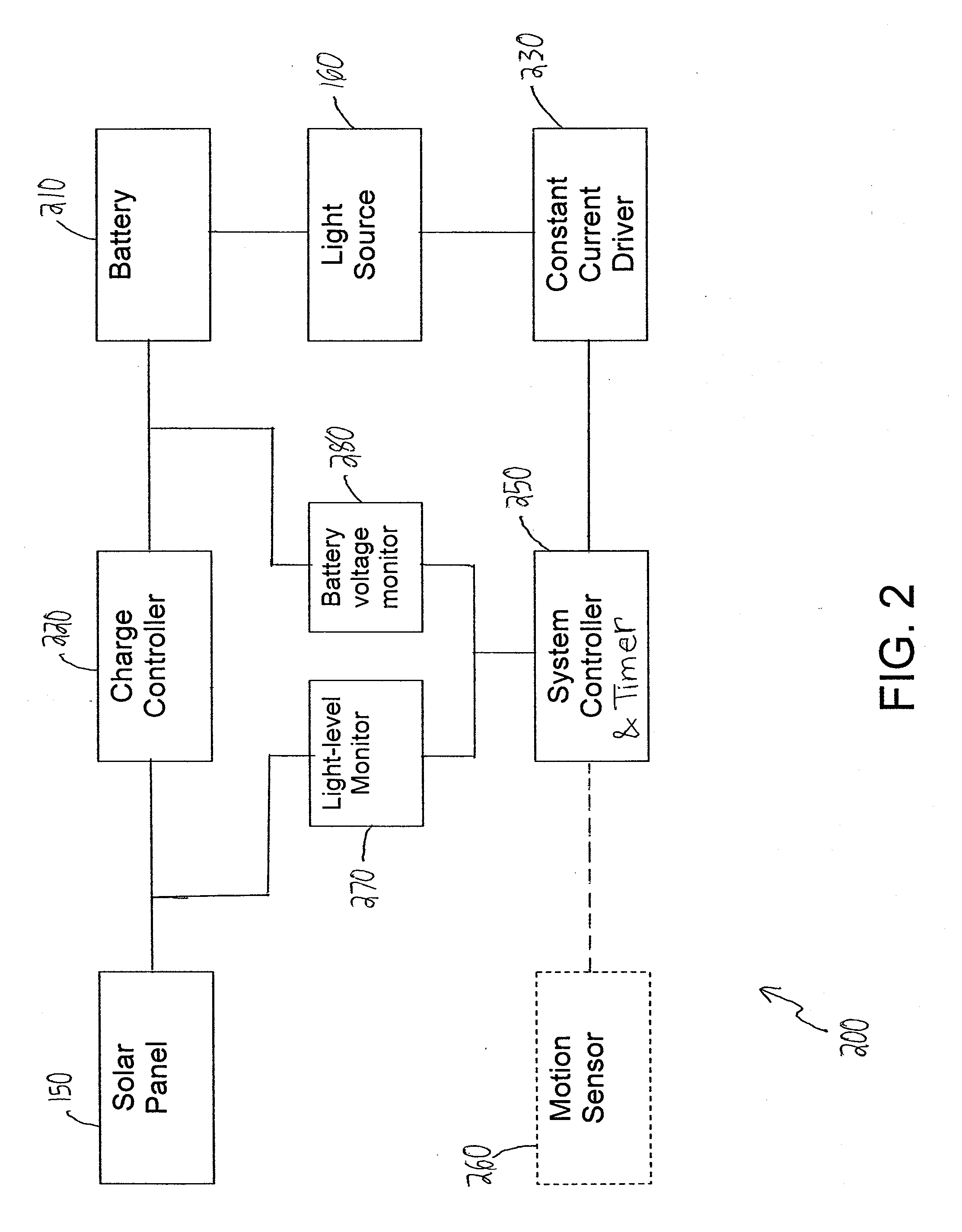
[0006]Embodiments of the present invention solve the problems of the solar-powered lighting features known in the art by providing a bollard that integrates the solar panel into one or more of its surfaces. This allows for a much larger solar panel to be used, which in turn increases the intensity and duration of light that can be generated through the light source. Embodiments of the present invention further address problems in the art by retaining the battery and other system components inside the bollard. By integrating those components, these embodiments allow for a larger, more efficient battery to be incorporated, which in turn increases the intensity and duration of light that can be generated through the light source. Some embodiments of the present invention further incorporate a charge controller and a timing device to increase the efficiency of the system by controlling factors that affect the battery life.
[0007]Embodiments of the present invention further improve over the prior art by incorporating light emitting diodes (LEDs) in the light source. LEDs are known in the art and are typically formed of a semiconductor diode. When an electric current passes through the diode, electrons are excited and release their energy as light. LEDs can be provided in a variety of colors. LEDs may be provided with integrated optical components to shape their radiation pattern and assist in reflection. LEDs typically generate very little heat, and may have lifetimes of 50,000 hours or more. These relatively low power usage and maintenance requirements make LEDs good candidates for external lighting applications.

Problems solved by technology

For these reasons, small lighting sources known in the art have been limited in the size of the solar panels and batteries they utilize.
This limitation has in turn constrained the amount of energy that can be captured and stored for later use by the lighting source.
Thus, lighting sources known in the art often have an intensity and operating time that is insufficient for many outdoor lighting applications.

Method used


Image

  • System and method for an outdoor lighting feature with an integrated solar panel
  • System and method for an outdoor lighting feature with an integrated solar panel
  • System and method for an outdoor lighting feature with an integrated solar panel

Examples


Embodiment Construction

[0055]At least one embodiment in accord with the present invention relates to a system and method for an outdoor lighting feature providing a bollard with an integrated solar panel, a battery and other components disposed within the bollard, and an LED light source for illuminating the terrain in the vicinity of the bollard.

[0056]The aspects disclosed herein, which are consistent with principles of the present invention, are not limited in their application to the details of construction and the arrangement of components set forth in the following description or illustrated in the drawings. These aspects are capable of assuming other embodiments and of being practiced or of being carried out in various ways. Examples of specific implementations are provided herein for illustrative purposes only and are not intended to be limiting. In particular, acts, elements, and features discussed in connection with any one or more embodiments are not intended to be excluded from a similar role i...


PUM


Abstract

A system and method for operating an outdoor lighting feature is provided, the outdoor lighting feature including a bollard, a solar panel disposed within a recess on the top of the bollard, a battery disposed within the bollard, the battery being electrically coupled to the solar panel and configured to receive and store energy from the solar panel, and a light source oriented to direct a light beam to a region external to the bollard, the light source being configured to draw an electric load from the battery. The system detects a change in an ambient light level, starts a timer and places a light source in a high-on state in response to the change in the ambient light level, monitors the timer, places the light source in a low-on state upon measuring a first predefined amount of lapsed time on the timer, and places the light source in an off state upon measuring a second predefined amount of lapsed time on the timer.

Description

BACKGROUND[0001]1. Field of the Invention[0002]The present invention relates generally to outdoor lighting features, and more specifically, to lighting features powered by solar energy.[0003]2. Discussion of Related Art[0004]Outdoor lighting is often desirable during nighttime hours for purposes of security, aesthetics, and avoiding injuries associated with walking on unlit terrain. Light sources may be provided in a variety of housings as dictated by location and aesthetics. As one example, pathway lights may be used to illuminate the ground near the light source in order to increase the visibility of a walkway or other outdoor area.[0005]To reduce the energy costs and labor associated with electrically coupling outdoor lighting to a domestic power supply, some outdoor lighting sources have been provided with solar panels or other mechanisms for generating energy without requiring a connection to the domestic power supply, as well as one or more batteries to store the power generat...

Claims


Application Information

Patent Timeline
IPC IPC(8): H05B37/02F21L4/00
CPCF21S8/083F21S9/035F21W2111/02F21W2111/023Y02B20/72F21Y2101/02H05B37/00H05B37/0227F21W2111/04F21Y2115/10H05B47/115H05B47/10H05B47/11Y02B20/40
Inventor METCHEAR, III, CHARLES R.PIPER, ELIZABETH K.
Owner METCHEAR III CHARLES R
Learn More