Venturi outlet turbine airfoil

Inactive Publication Date: 2005-11-29
GENERAL ELECTRIC CO
View PDF11 Cites 46 Cited by
  • Summary
  • Abstract
  • Description
  • Claims
  • Application Information

AI Technical Summary

Benefits of technology

[0018]Accordingly, it is desired to provide a turbine airfoil having an improved trailing edge cooling design for increasing cooling efficiency

Problems solved by technology

And, the airfoils are subject to complex stress distribution at the different parts thereof due to the complex temperature distribution.
The cooling configurations of the turbine airfoils are also dependent on the physical size of the airfoils from large to small, with the smaller airfoils having additional problems for efficient cooling thereof due to the practical lower limit in size of cooling features which may be introduced therein.
However, for particularly small turbine airfoils on the order of several centimeters in span height, the introduction of even the minimum-size outlet hole, on the order of about 10-15 mils in diameter, may require the placement of the trailing edge holes significantly upstream from the trailing edge itself, which decreases the cooling effectiveness of the disc

Method used


Image

  • Venturi outlet turbine airfoil
  • Venturi outlet turbine airfoil
  • Venturi outlet turbine airfoil

Examples


Example

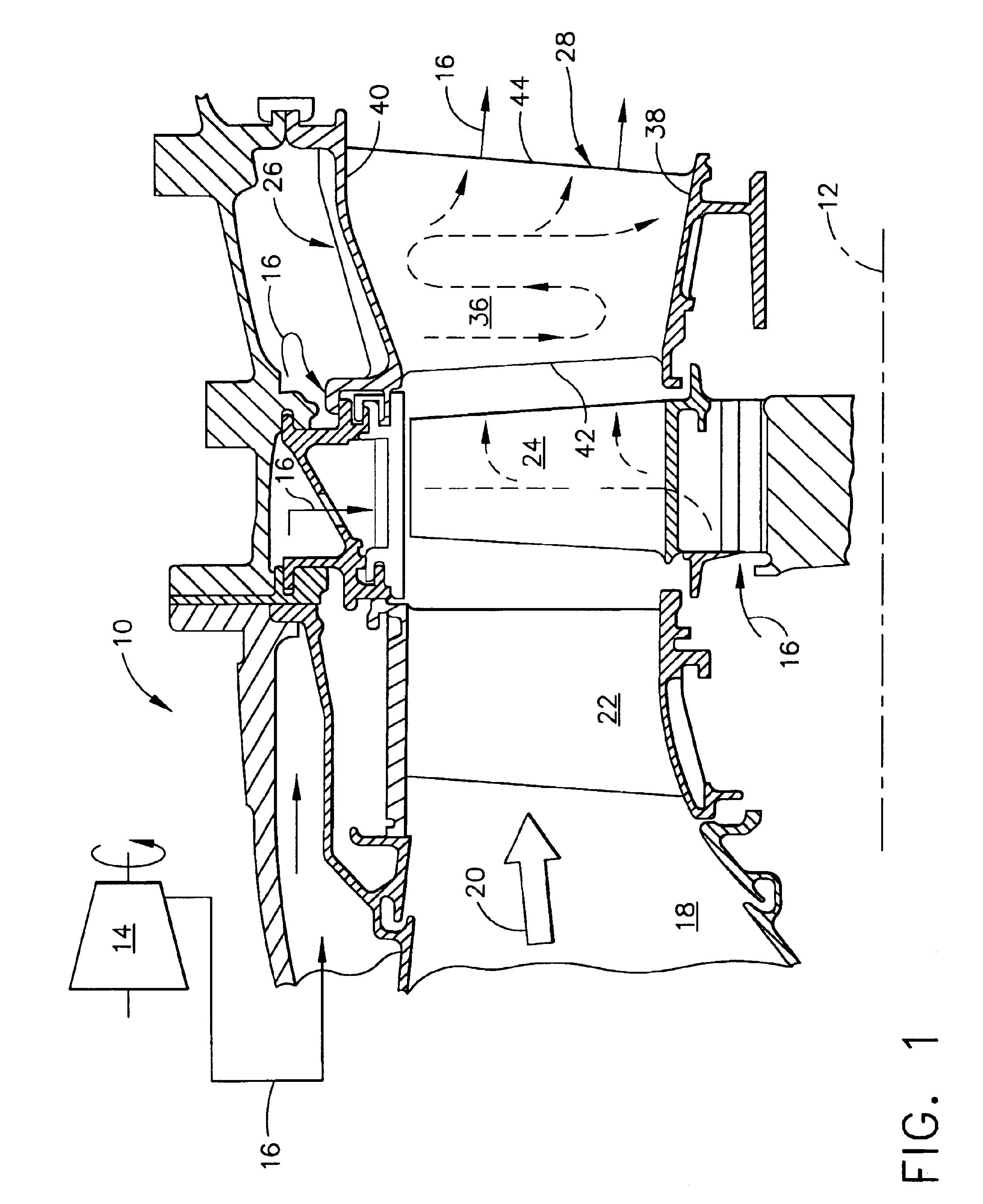
[0029]Illustrated in FIG. 1 is a portion of an exemplary turbofan gas turbine engine 10 which is axisymmetrical about a longitudinal or axial centerline axis 12. The engine includes a multistage axial compressor 14 configured for pressurizing air 16 which is suitably channeled to an annular combustor 18, illustrated in aft part.

[0030]Fuel is mixed with the compressed air in the combustor in a conventional manner for generating hot combustion gases 20 which flow downstream therefrom.

[0031]A high pressure turbine includes a first stage turbine nozzle 22 which channels the combustion gases from the combustor through a row of first stage turbine rotor blades 24 which extract energy therefrom. The blades extend radially outwardly from a supporting disk which is joined by a shaft to the compressor for rotating the several stages of compressor rotor blades therein during operation.

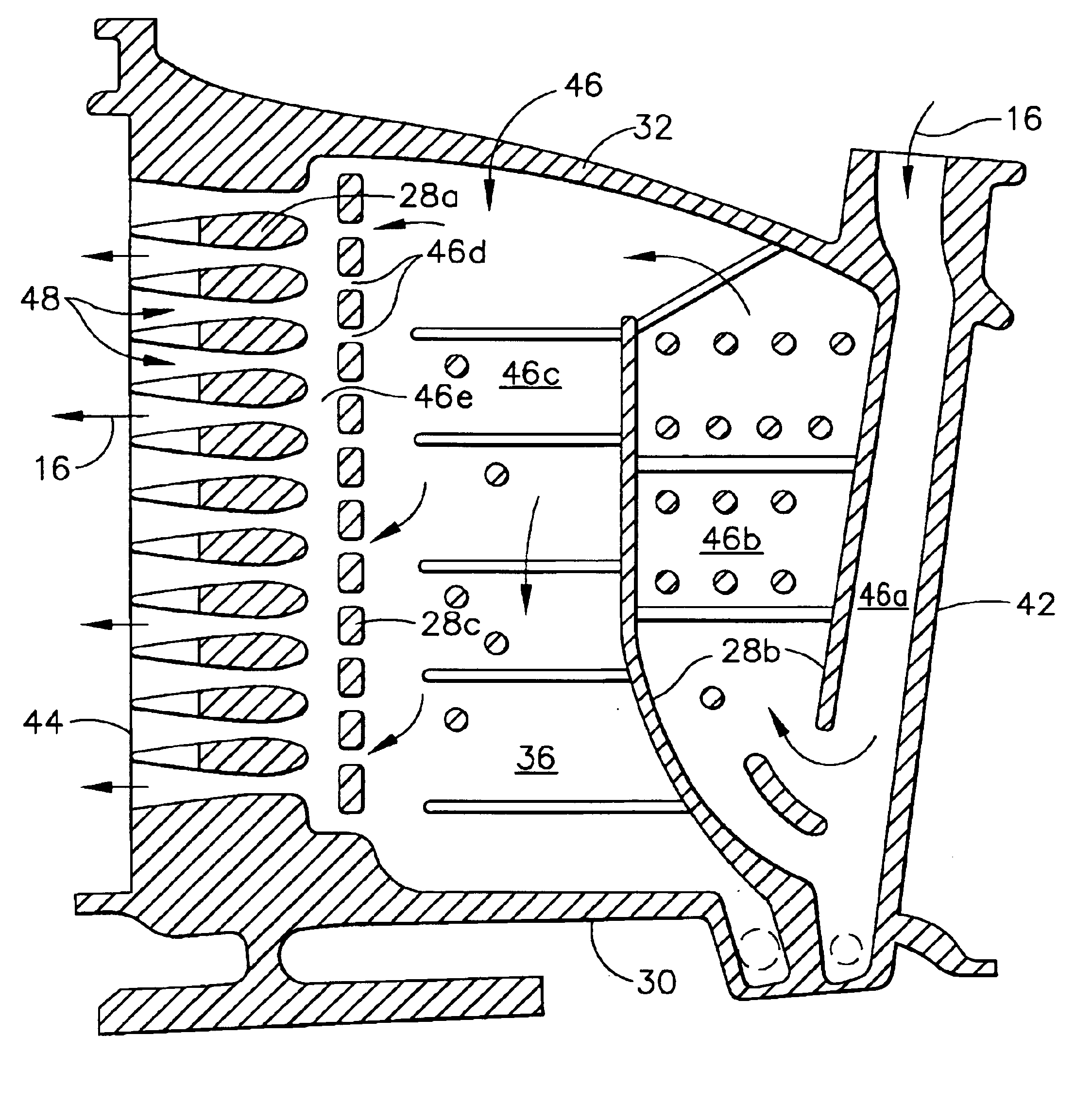
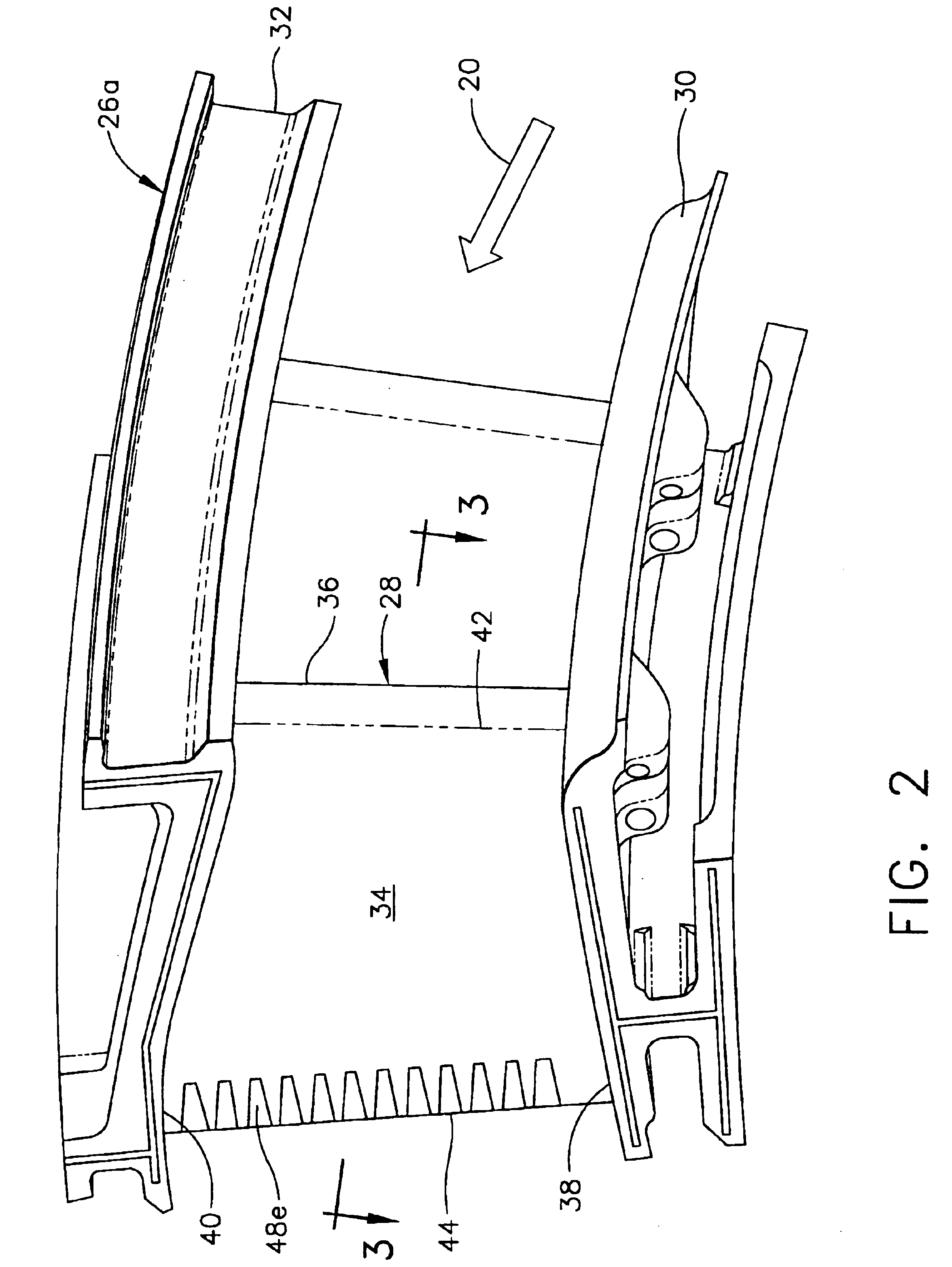
[0032]Disposed immediately downstream of the first stage rotor blades is a second stage turbine nozzle 26 conv...


PUM


Abstract

A turbine airfoil includes sidewalls extending between leading and trailing edges, with an internal cooling circuit therein. A row of venturi slots commences inside the airfoil at the cooling circuit and terminates near the trailing edge. Each of the venturi slots includes an inlet, converging portion, throat, diverging portion, and outlet in serial flow communication from the cooling circuit. The converging portion is comparable in chordal length with the throat.

Description

BACKGROUND OF THE INVENTION[0001]The present invention relates generally to gas turbine engines, and, more specifically, to turbines therein.[0002]In a gas turbine engine, air is pressurized in a compressor and mixed with fuel in a combustor for generating hot combustion gases which flow downstream through turbines that extract energy therefrom. High and low pressure turbines extract energy in turn for correspondingly powering the compressor and providing useful work, such as powering an upstream fan in an exemplary turbofan engine for powering an aircraft in flight.[0003]In aircraft applications, engine weight and efficiency are primary design objectives for maximizing aircraft range and reducing operating costs. Weight and efficiency are interrelated in the various highly sophisticated components of the modern gas turbine engine built with precision typically measured in mils, and even fractions of mils.[0004]Rotary turbine blades and stationary turbine nozzle vanes have correspon...

Claims


Application Information

Patent Timeline
IPC IPC(8): F01D5/18F01D9/02
CPCF01D5/187Y02T50/671Y02T50/673Y02T50/676F05D2250/323F05D2250/52F05D2230/21F05D2260/221F05D2250/324Y02T50/60
Inventor SHI, BAOLANMANNING, ROBERT FRANCISRYDBECK, RANDALL BRENT
Owner GENERAL ELECTRIC CO
Why Eureka
Try Eureka