
Apparatus and method for improved energy dispersive X-ray spectrometer

Inactive Publication Date: 2002-08-27
OHARA DAVID B
View PDF2 Cites 50 Cited by
  • Summary
  • Abstract
  • Description
  • Claims
  • Application Information

AI Technical Summary

Benefits of technology

Accordingly, several objects and advantages of the present invention are:
a) to solve the practical problem of increasing the efficiency of x-ray detection in an energy dispersive x-ray spectrometer by gathering x-rays that are diverging away and redirecting them through an aperture;
b) to provide an energy dispersive x-ray

Problems solved by technology

Unfortunately, EDS systems are frequently inefficient at detection of very low energy x-rays and this inefficiency is exacerbated by the low production rate of low energy x-rays compared to higher energy ones.
Because of the low production rate of these low energy x-rays compared to higher energy ones, an EDS system spends most of its time counting pulses from higher energy x-rays, thus adversely affecting the instrument's detection limit for the light elements, thereby making these elements detectable by EDS only when found in relatively high concentration in the sample.
The x-ray lines for the light elements are closer in energy than those for the heavier elements and many EDS systems have difficulty resolving these x-ray lines when L lines from heavier elements are also emitted by the sample.
In some cases, the size of the detector is limited by the instrument's geometry, so that a smaller detector is necessary even when poor resolution occurs.
For example, some electron microscopes have sufficiently close working distances or otherwise poor access to x-rays emitted from a sample, that either a very small detector must be used or the detector must be placed far from the x-ray source.

Method used


Image

  • Apparatus and method for improved energy dispersive X-ray spectrometer
  • Apparatus and method for improved energy dispersive X-ray spectrometer
  • Apparatus and method for improved energy dispersive X-ray spectrometer

Examples


Embodiment Construction

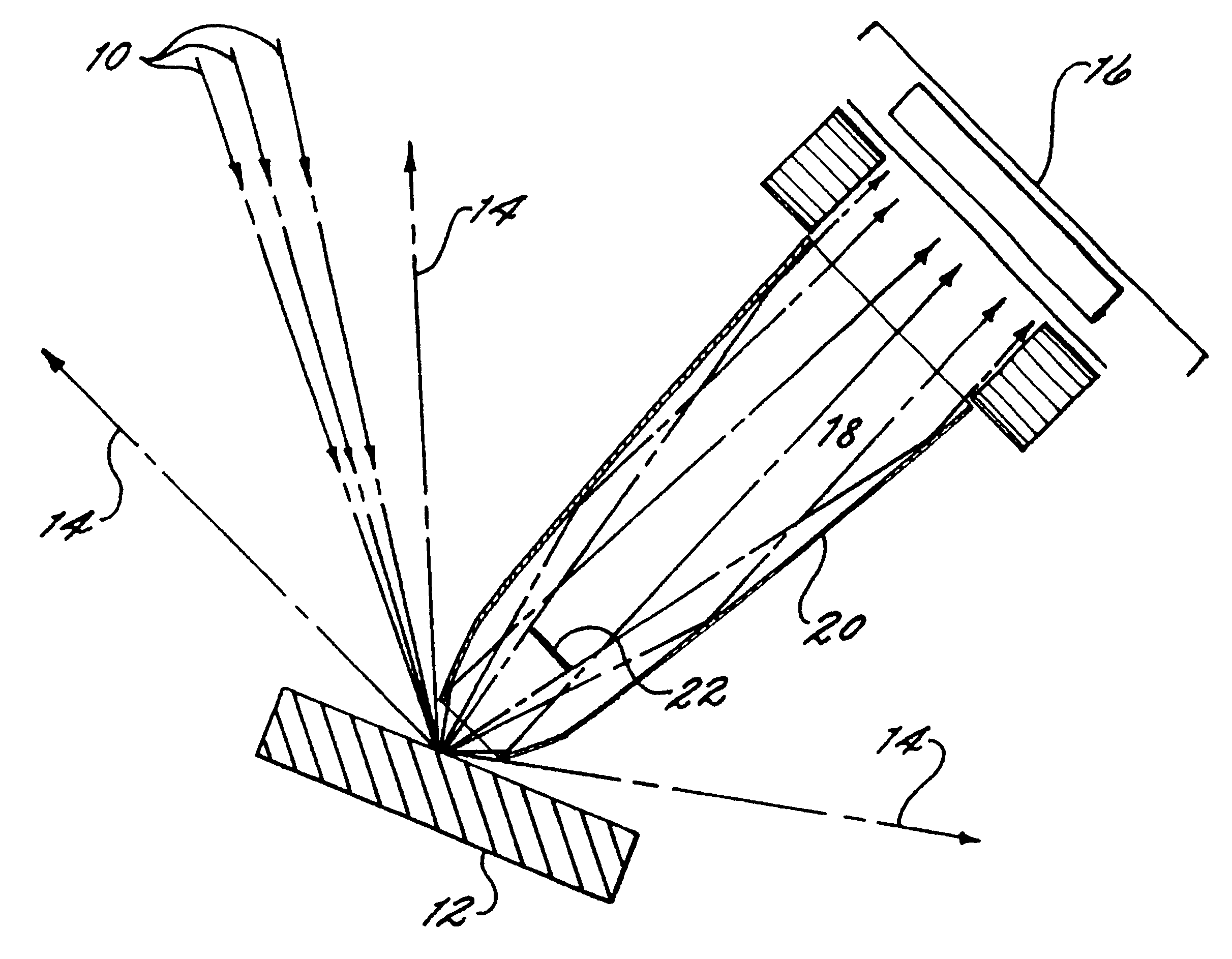
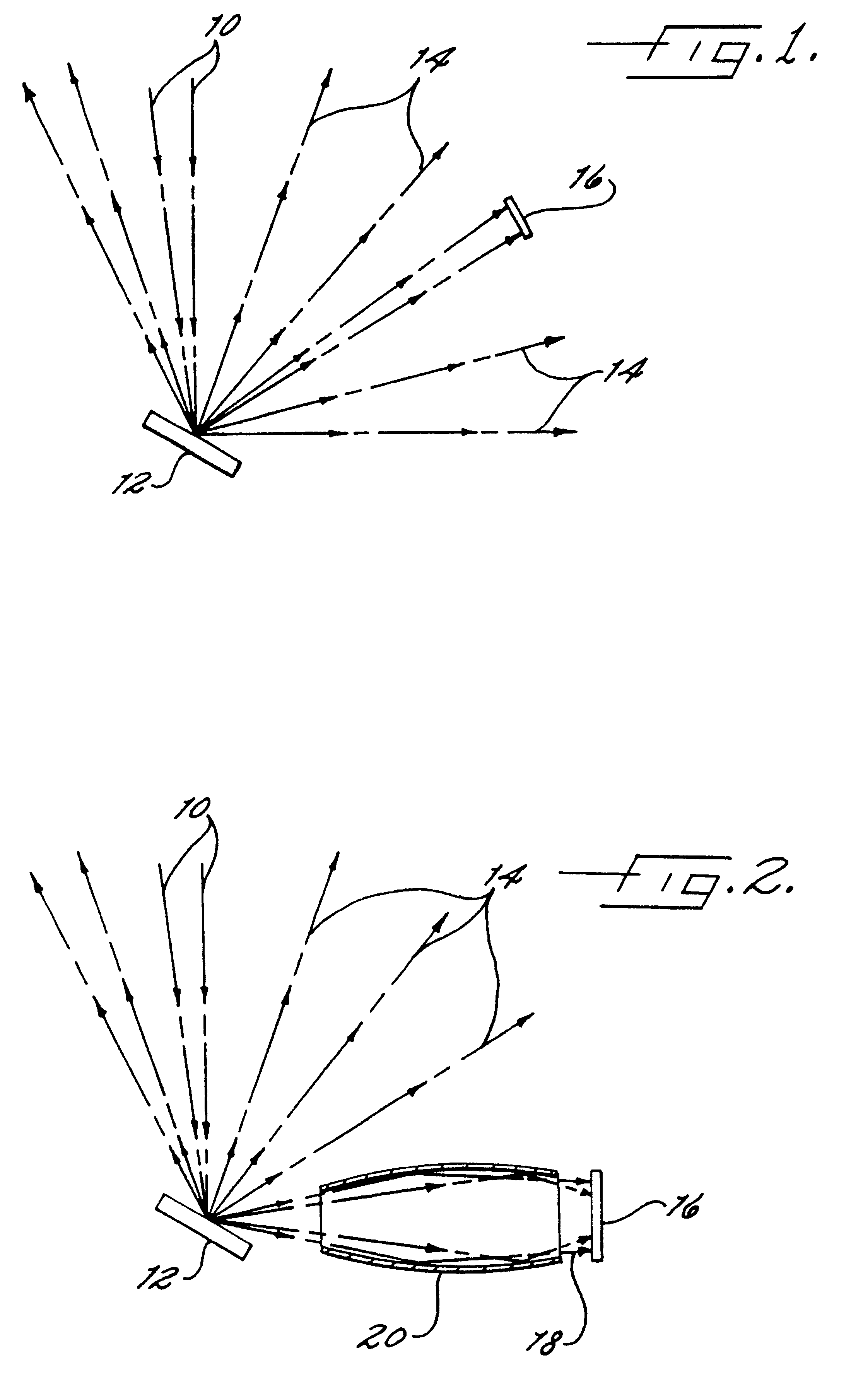
The invention disclosed in this patent application concerns a method of improving an energy dispersive x-ray spectrometer (EDS) through the use of a reflecting optic 20 by collecting through an entrance aperture 24 the isotropic x-rays 14 emitted from the target sample 12 and guiding those redirected x-rays 18 through an exit aperture 26 onto the x-ray detector 16. The optics 20 herein described, when fitted with a stop 22 at or near the entrance aperture 24, may also be used in the EDS as low-pass filters that reduce the number of higher energy x-rays reaching the detector 16 and may be used as well to spatially define the area of the target sample 12 from which emitted x-rays 14 are selected for analysis.

The optics 20 described in this application are specifically of the type known as "grazing incidence optics", which use the principle of total external reflection for the efficient collection of x-rays. Grazing incidence optics have been used for other x-ray spectroscopy applicati...


PUM


Abstract

The invention is an improved energy dispersive x-ray spectrometer comprising x-ray source (10), sample (12), optics (20) and detector (16). The improvement comprises the use of optics using the principle of total external reflection for delivering an increased flux of x-rays onto the detector. These flux concentrating optics are generally shaped as tubes having a figure of revolution as a longitudinal cross section such as a cone, parabola, hyperbola, ellipsoid and others. These optics may also be used as low energy pass filters by incorporating a stop (22) at or near the aperture of the optic. The reflecting surface of the flux concentrator optic may be selected from the group of metals and their alloys, the choice made to optimize the optic's performance.

Description

1. Field of InventionThis invention relates to the field of x-ray spectrometry and other instrumentation relying on energy dispersive spectrometry analysis of x-rays emitted from a target, and specifically to a method and apparatus for preserving the flux of x-rays emitted from said target and available for analytical purposes within the instrument.2. Description of Prior ArtIn x-ray spectroscopic elemental analyses, there are two main techniques for separating into their various energies the x-rays emitted from the sample under analysis, these are wavelength dispersive spectroscopy (WDS) and energy dispersive spectroscopy (EDS).WDS uses Bragg reflection from a crystal to separate the x-rays into various wavelengths, while EDS uses a solid state device whose output is a known function of the x-ray energy to separate them into various energy bins. For reasons of mechanical simplicity, data collection times, spectrometer size and various other technical reasons, EDS is frequently pref...

Claims


Application Information

Patent Timeline
IPC IPC(8): G01N23/22G01N23/223G21K1/00G21K1/06G01N23/20G01N23/201
CPCG01N23/20025G01N23/201G01N23/223G21K1/06G01N2223/076
Inventor O'HARA, DAVID B.
Owner OHARA DAVID B
Learn More