Multi-Purpose Ice Axe Including Rotating Spike

Active Publication Date: 2015-11-19
2THINK
View PDF1 Cites 8 Cited by
  • Summary
  • Abstract
  • Description
  • Claims
  • Application Information

AI Technical Summary

Benefits of technology

[0005]A broad object of embodiments of the invention can be to provide a spike including a rotary position se

Problems solved by technology

Additionally, conventional ice axes may not allow selectable fixed angular positioning of the spike in relation to the shaft of the ice axe.
There can be disadvantag

Method used


Image

  • Multi-Purpose Ice Axe Including Rotating Spike
  • Multi-Purpose Ice Axe Including Rotating Spike
  • Multi-Purpose Ice Axe Including Rotating Spike

Examples


Embodiment Construction

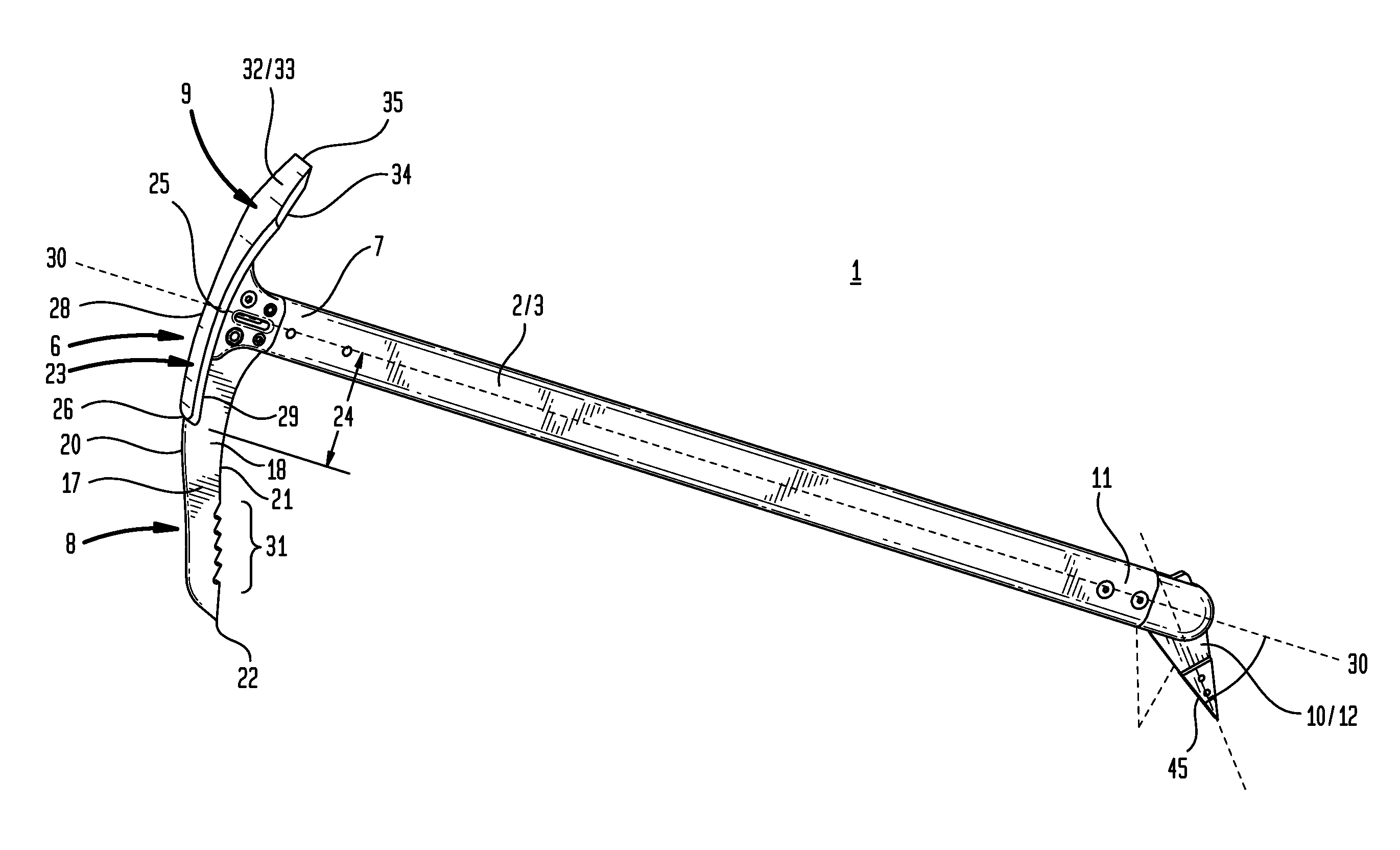
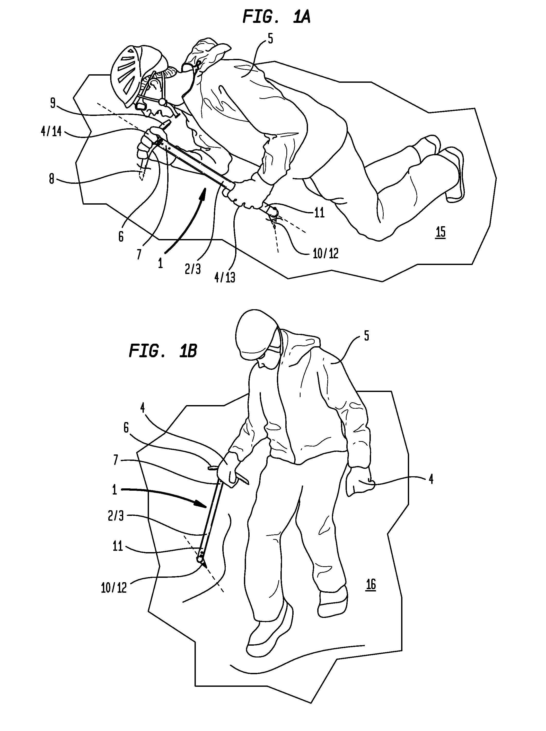
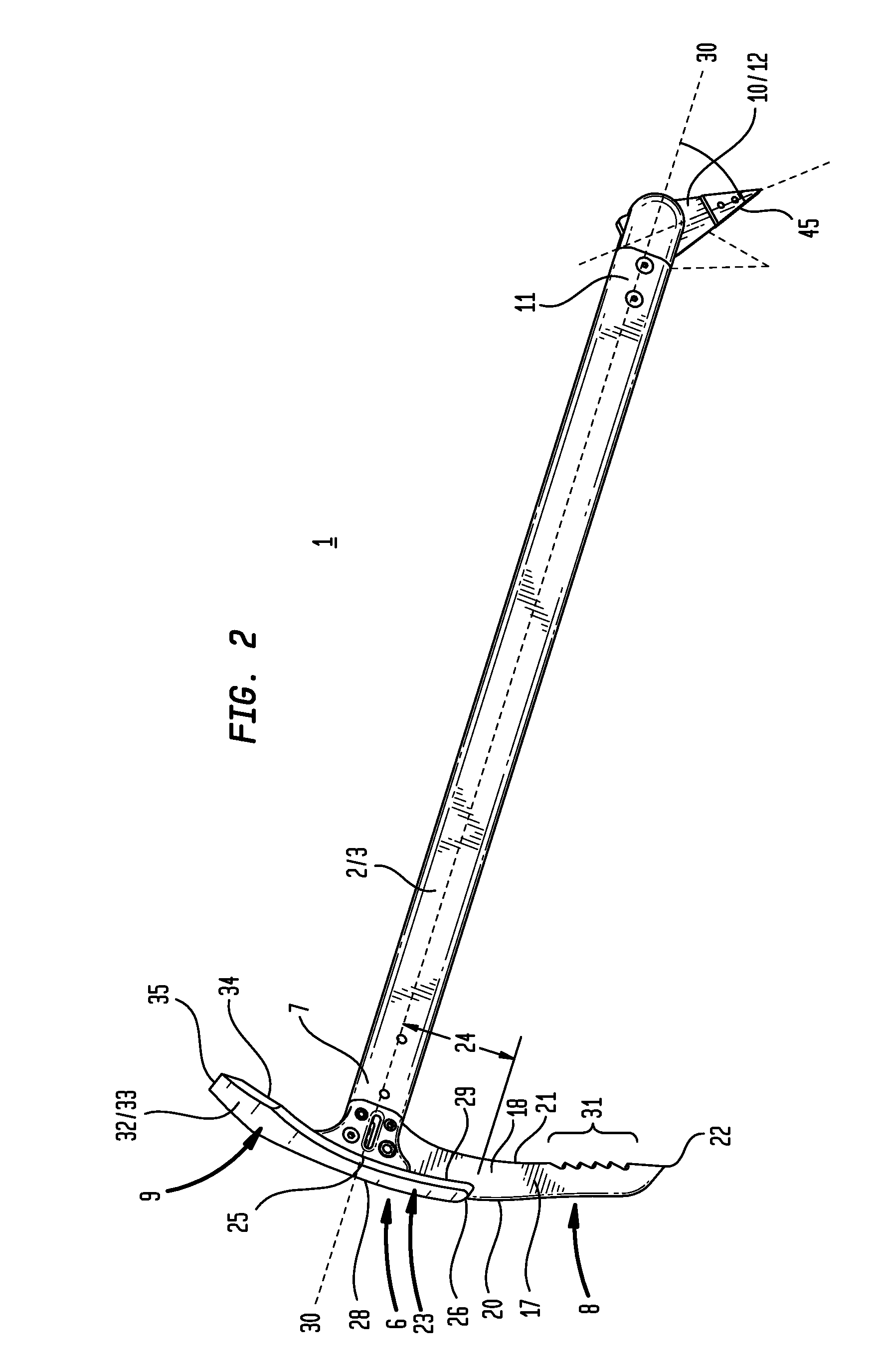
[0034]Now referring to FIG. 1A, embodiments of the inventive ice axe (1) include one or more of: a shaft (2) having a shaft external surface (3) configured for gripping engagement by one of pair of hands (4) of a user (5), a head (6) coupled to a shaft first end (7) including an inventive pick (8) or an inventive adze (9) which outwardly extend from the shaft first end (7), and a spike (10) rotatably coupled to a shaft second end (11) which allows selectable fixed angular positioning of the spike (10) in relation to the shaft (2).

[0035]FIG. 1A further shows an illustrative method for use of the inventive ice axe (1) having the spike (10) established in a fixed angular position (12) to the shaft (2). The user (5) can grip the shaft (2) in a first hand (13) and grip the head (6) in a second hand (14). The pick (8) can be driven into a snow or ice slope (15)(or other slope) and the spike (10) can be driven into the snow or ice slope (15) to arrest the user's (5) slide upon the snow or ...


PUM


Abstract

Generally, a spike including a rotary position selector which allows selectable incremental fixed angular positioning of the spike, the spike adaptable to couple to a tool. Specifically, an ice axe having a rotatable spike which allows selectable fixed angular positioning of the spike in relation to the shaft of the ice axe.

Description

I. FIELD OF THE INVENTION[0001]Generally, a spike including a rotary position selector which allows selectable incremental fixed angular positioning of the spike, the spike adaptable to couple to a tool. Specifically, an ice axe having a rotatable spike which allows selectable fixed angular positioning of the spike in relation to the shaft of the ice axe.II. BACKGROUND OF THE INVENTION[0002]Conventional ice axes typically include a head and a spike fixedly coupled to opposite ends of a shaft. The spike tip typically aligns with the central longitudinal axis of the shaft to provide a spike which linearly extends from the shaft end. Additionally, conventional ice axes may not allow selectable fixed angular positioning of the spike in relation to the shaft of the ice axe. Moreover, the head of conventional ice axes may include a pick having a planate blade lacking any orthogonal element coupled to the blade top edge and a planate adze lacking any orthogonal element.[0003]There can be d...

Claims


Application Information

Patent Timeline
IPC IPC(8): A63B29/08B25F1/00B25D7/00B26B23/00
CPCA63B29/08B25D7/00B25F1/00B26B23/00
Inventor WILLEY, KEVIN E.
Owner 2THINK
Why Eureka
Try Eureka