Target Holder

Inactive Publication Date: 2015-11-19
FERRELL ROGER H
View PDF4 Cites 24 Cited by
  • Summary
  • Abstract
  • Description
  • Claims
  • Application Information

AI Technical Summary

Problems solved by technology

Use of a solid structure to hold the targe...

Method used


Image

  • Target Holder
  • Target Holder
  • Target Holder

Examples


Embodiment Construction

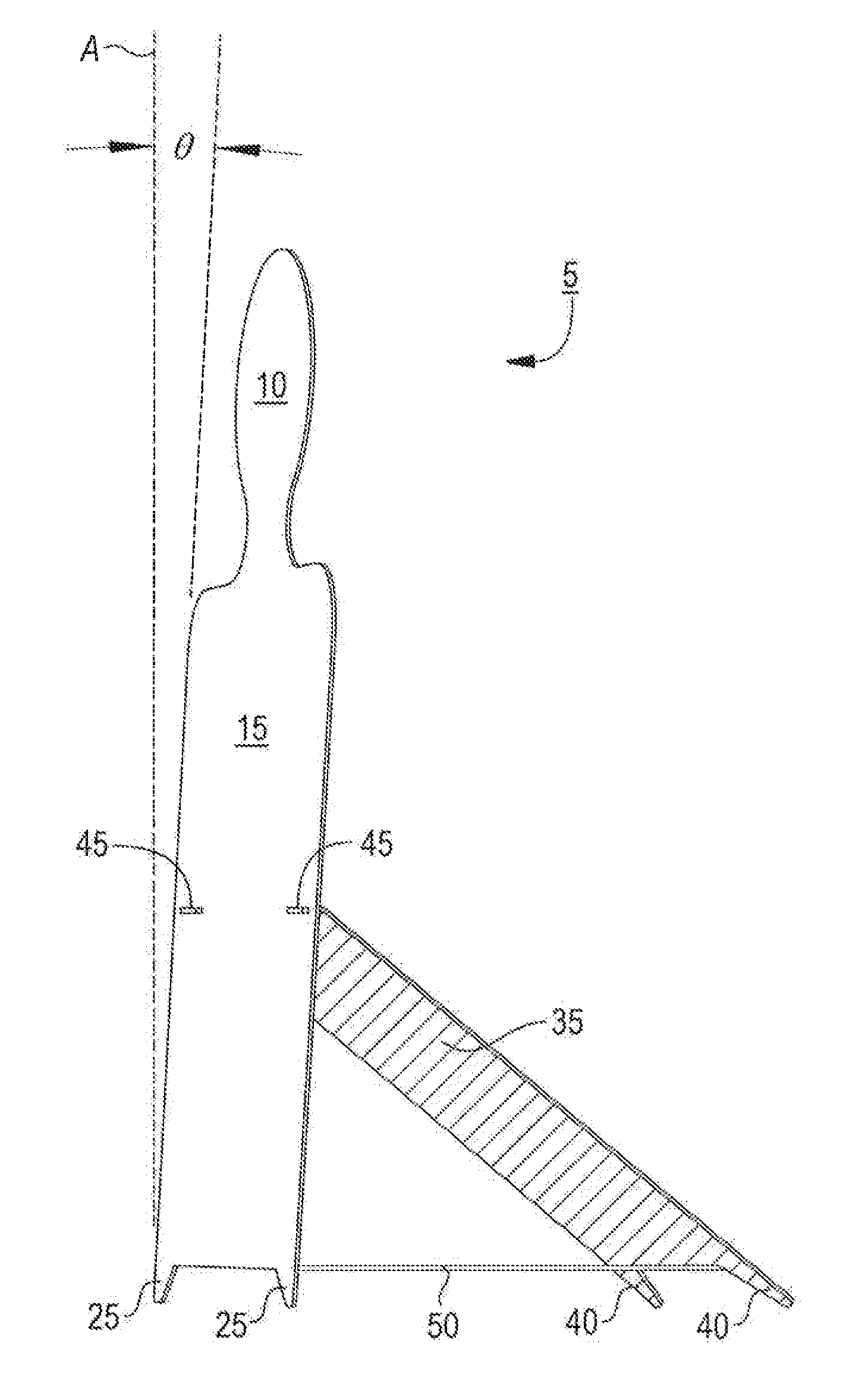
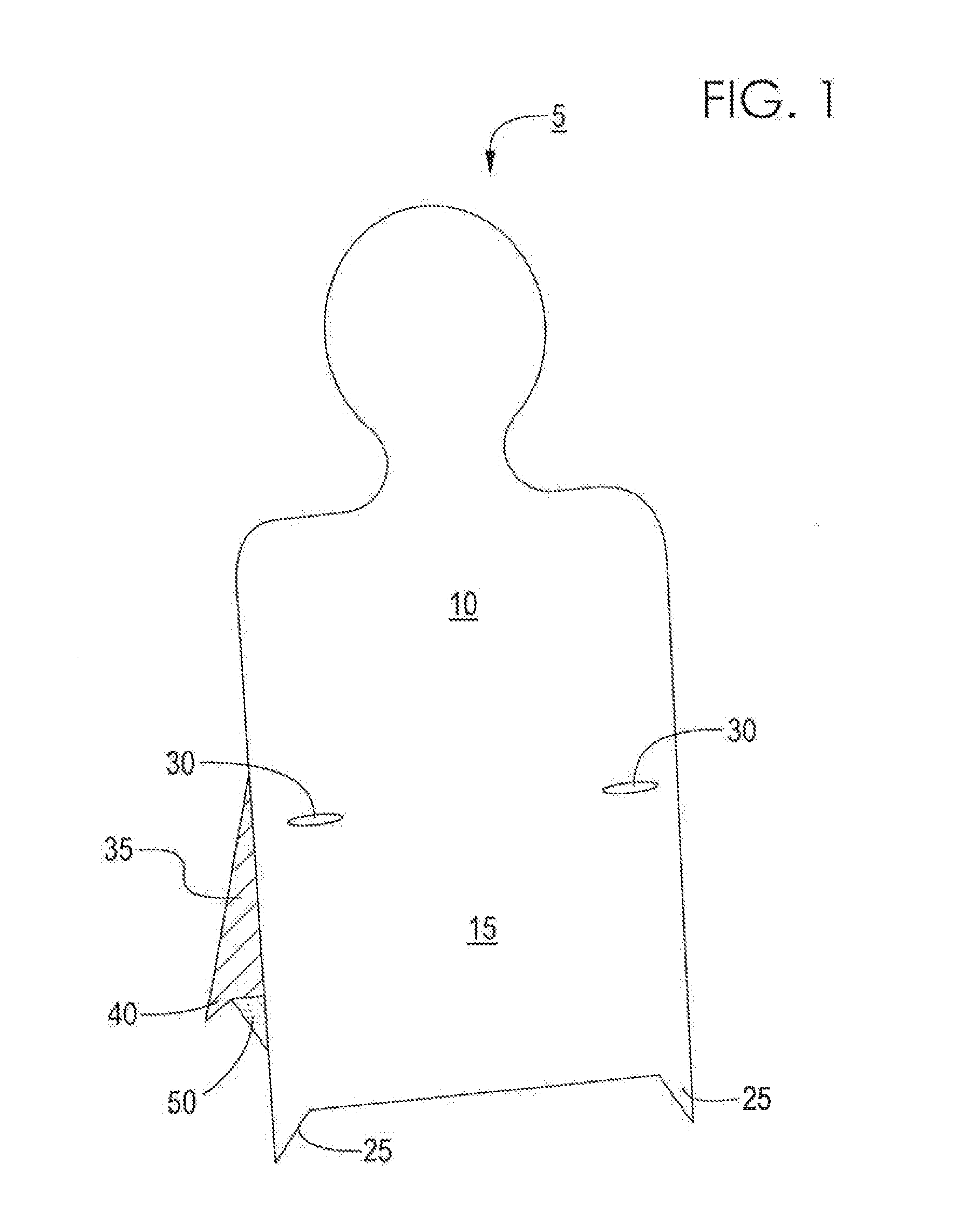
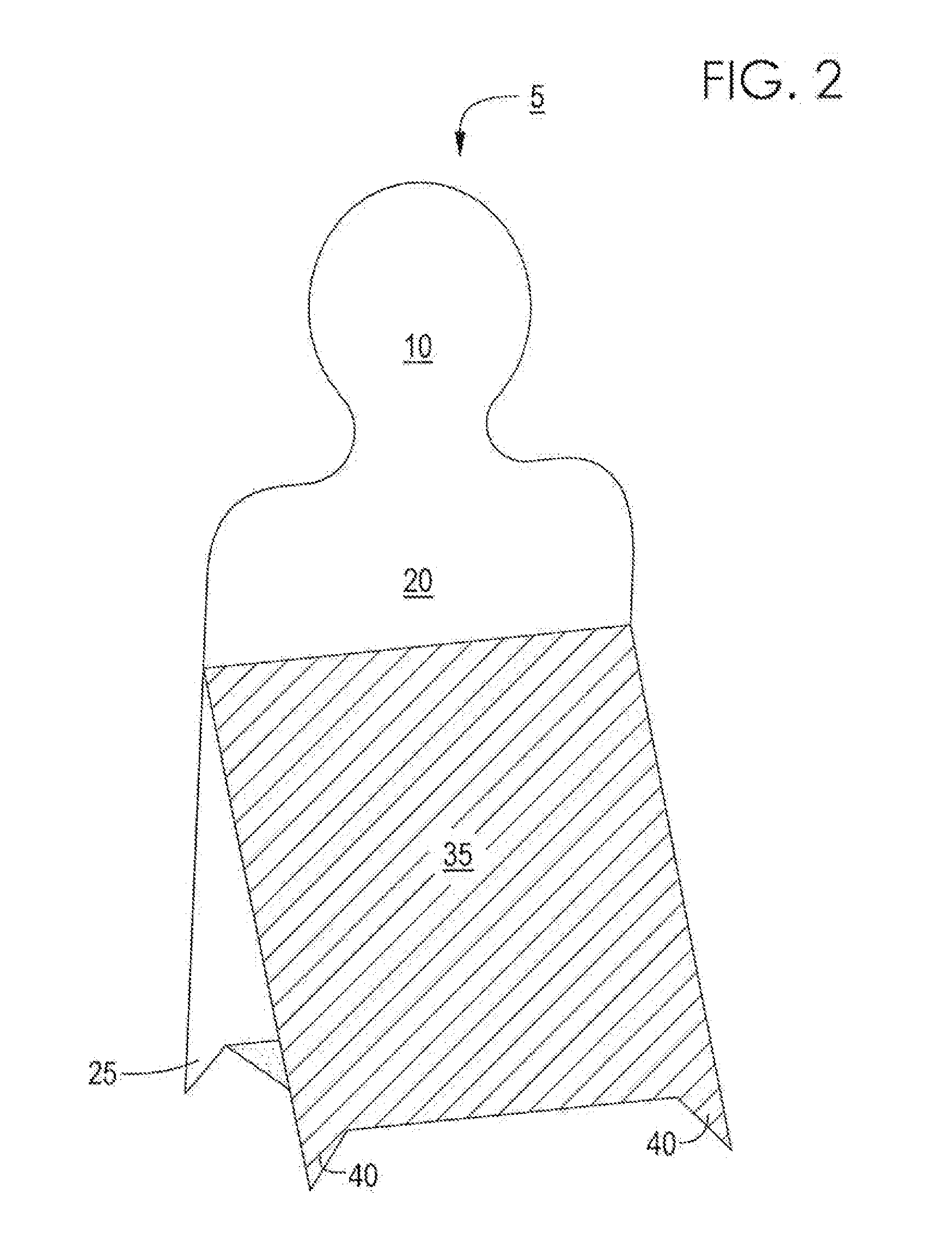
[0011]The present disclosure provides a target holder 5 that is portable, lightweight, economical and disposable that will facilitate more effective and safer shooting practice in the field. Now referring to FIGS. 1-6, in one embodiment, the target holder 5 comprises a front panel 10, a support 35 and a horizontal connector 50.

[0012]With continuing reference to FIGS. 1-3, the front panel 10 further comprises a front surface 15 that faces the marksman, a rear surface 20, one or more legs 25 and one or more slots 30. The front surface 15 is directed towards the marksman during use and may optionally be inclined at angle θ from vertical axis A as shown in FIG. 3. In one embodiment, angle θ is approximately between 1-45 degrees, while in an alternate embodiment angle θ is approximately between 1 and 20 degrees, while in yet another embodiment angle θ is between 1 and 10 degrees.

[0013]The one or more slots 30 are configured or adapted to receive one of more tabs 45 (as discussed below). ...


PUM


Abstract

The present disclosure provides a target holder 5 having a front panel 10 comprising a front surface 15, a rear surface 20, one or more legs 25 and one or more slots 30, a support 35 comprising one or more tabs 45 and one or more legs 40, and a horizontal connector 50, wherein the one or more tabs 45 are configured to engage the one or more slots 30 and further wherein the front 10, support 35 and horizontal connector 50 are of integral construction. Also provided herein is a target practice kit having a target holder and a target, wherein the target is secured to the target holder via a target securing means.

Description

FIELD OF THE DISCLOSURE[0001]The present disclosure pertains to the field of firearm shooting accessories. More specifically, the present disclosure pertains to a target holder.BACKGROUND[0002]Marksmen practice their skills by shooting at disposable or paper targets, often the commonly known “bull's-eye” target. Marksmen may practice either at a dedicated shooting facility, such as a gun range, or they may prefer to practice in the field which better simulates real world conditions more accurately than a gun range. When practicing in the field, marksmen often will attach their targets to trees, wooden posts, fence rails or other solid structures. Often, these are placed in front of hills, dirt mounds or other natural or man-made barriers for serving as a backstop to arrest the motion of the bullet. Use of a solid structure to hold the target could cause ricochets, which is not desirable. There exists a need for a portable, lightweight, economical and disposable target holder that wi...

Claims


Application Information

Patent Timeline
IPC IPC(8): F41J1/10
CPCF41J1/10
Inventor FERRELL, ROGER H.
Owner FERRELL ROGER H
Why Eureka
Try Eureka