Image processing device, display apparatus, and image processing method

a technology for image processing and display apparatus, applied in image analysis, image memory management, instruments, etc., can solve the problem of increasing the cost of the image processing circuit, and achieve the effect of reducing the time required to obtain the data used for correction

Active Publication Date: 2015-12-03
SEIKO EPSON CORP
View PDF3 Cites 3 Cited by
  • Summary
  • Abstract
  • Description
  • Claims
  • Application Information

AI Technical Summary

Benefits of technology

[0022]According to the above image processing method, the time required to obtain data used for correction can be shortened without use of a high-speed clock for memory access.

Problems solved by technology

The above technique has a problem that the necessity of generating a high-speed clock increases the cost of the image processing circuit.

Method used


Image

  • Image processing device, display apparatus, and image processing method
  • Image processing device, display apparatus, and image processing method
  • Image processing device, display apparatus, and image processing method

Examples


Embodiment Construction

.

[0036]FIG. 13 is a view showing Operation Example 2.

[0037]FIG. 14 is a view showing Operation Example 3.

[0038]FIG. 15 is a view showing Operation Example 4.

[0039]FIG. 16 is a view showing a state where Cr=1 and Cw=121.

[0040]FIG. 17 is a view showing a state where Cr=120 and Cw=241.

[0041]FIG. 18 is a view showing a state where Cr=200 and Cw=321.

[0042]FIG. 19 is a view illustrating allocation of memory areas to two frame buffers.

[0043]FIG. 20 is a view illustrating correction of the position Pd in Variation 4.

DESCRIPTION OF EXEMPLARY EMBODIMENTS

1. Configuration

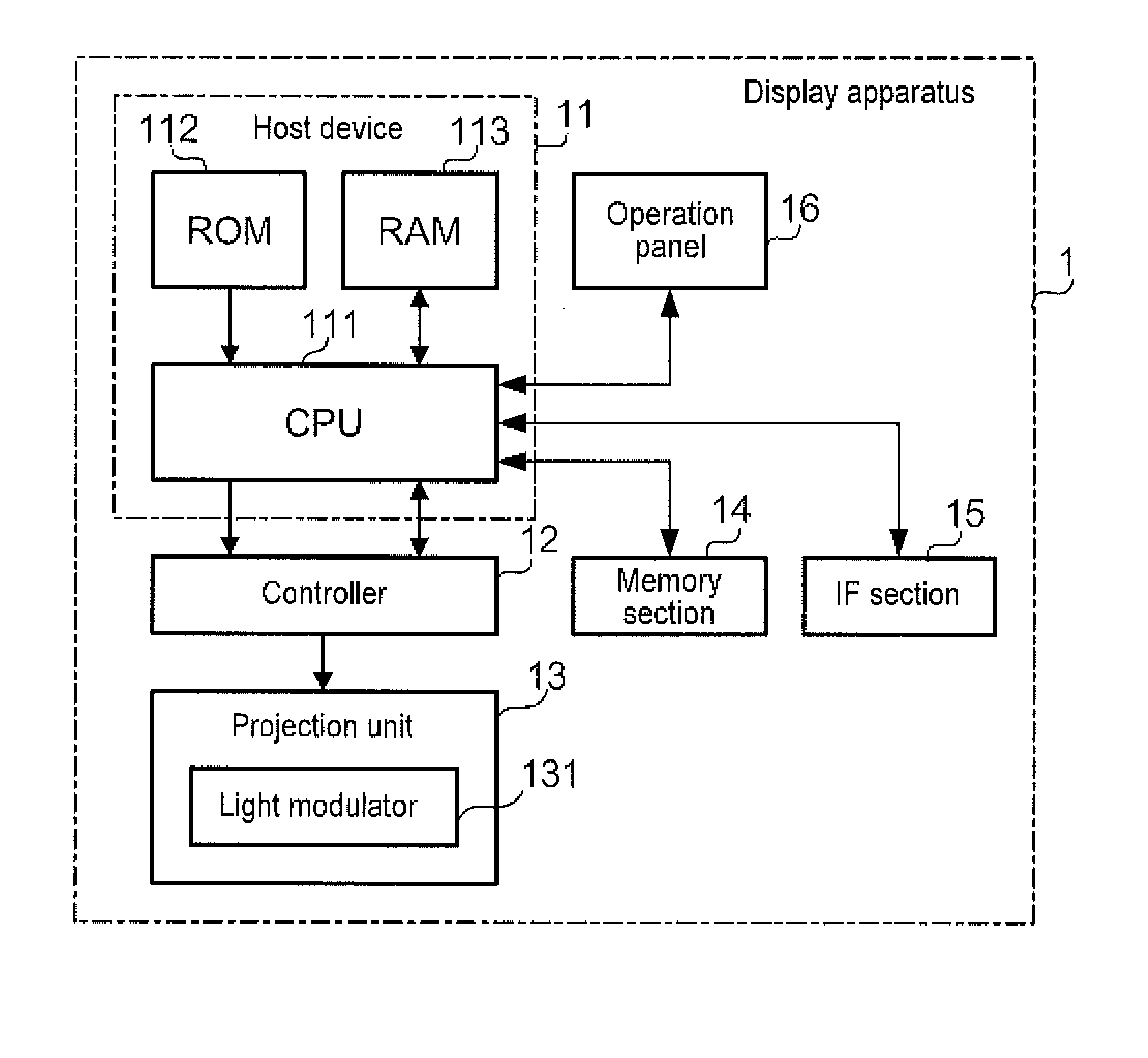
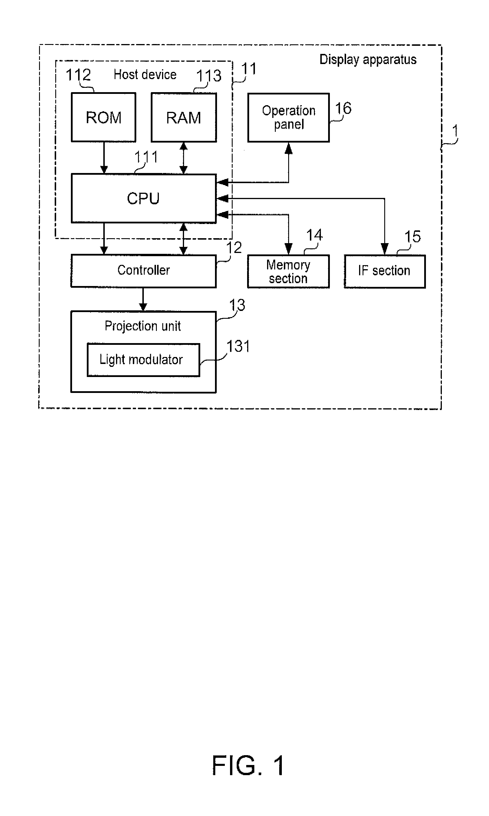
[0044]FIG. 1 is a block diagram showing a configuration of a display apparatus 1 according to an embodiment. The display apparatus 1 is a projective display apparatus that projects an image on a windshield of an automobile, a train, or a plane, for example, which is a so-called head-up display (HUD). When the display apparatus 1 is used for an automobile, the image projected is an image of a screen of a car navigation system or...


PUM


Abstract

An image processing device includes: a first memory section that has memory areas equivalent to data of k1 rows of an image and stores data of at least two adjoining pixels in each of the memory areas; a second memory section that has memory areas equivalent to data of k2 rows of the image and stores data of at least two adjoining pixels in a row different from pixels of which data is stored in the first memory section in each of the memory areas; and a correction section that corrects data of an object pixel, out of pixels of r rows×c columns, using data of a plurality of pixels stored in a memory area corresponding to a position designated by an offset vector corresponding to the object pixel in the first and second memory sections.

Description

BACKGROUND[0001]1. Technical Field[0002]The present invention relates to a technology for correcting images.[0003]2. Related Art[0004]In a projector, when the positional relationship between a screen and a projection system is deviated from an ideal state, the image projected on the screen is distorted. To cancel out this distortion, image processing of imparting a distortion opposite to the existing distortion to the input image is used. This image processing is performed for a pixel to be processed of the input image by referring to data of another pixel at a position designated by an offset vector corresponding to the pixel to be processed. In this case, when the components of the offset vector are not integers, the image processing is performed referring to data of four pixels around the position designated by the offset vector.[0005]To perform image processing using data of four pixels, it is naturally required to read data of four pixels from a memory. That is, it is necessary...

Claims


Application Information

Patent Timeline
Patent Type & Authority Applications(United States)
IPC IPC(8): G06T7/00
CPCG06T7/0026G06T7/0034G06T1/60G06T3/0093G06T3/00
Inventor HAYASHI, TADASHI
Owner SEIKO EPSON CORP
Why Eureka
Try Eureka