

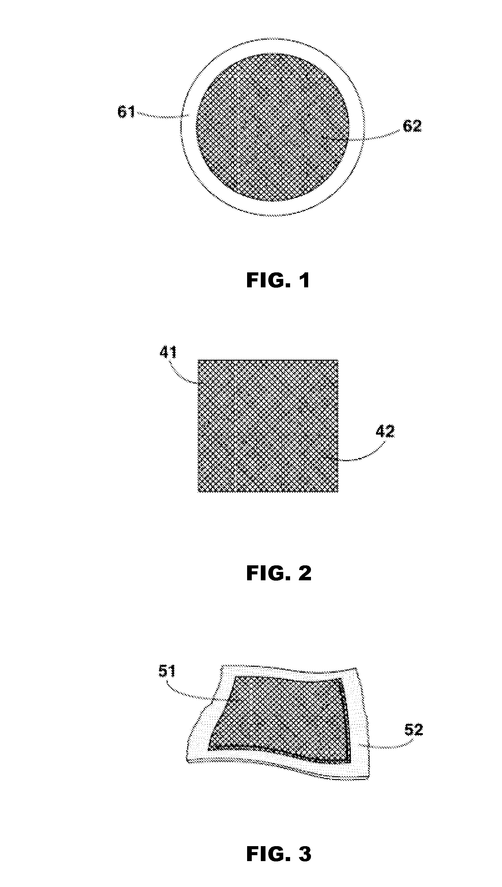
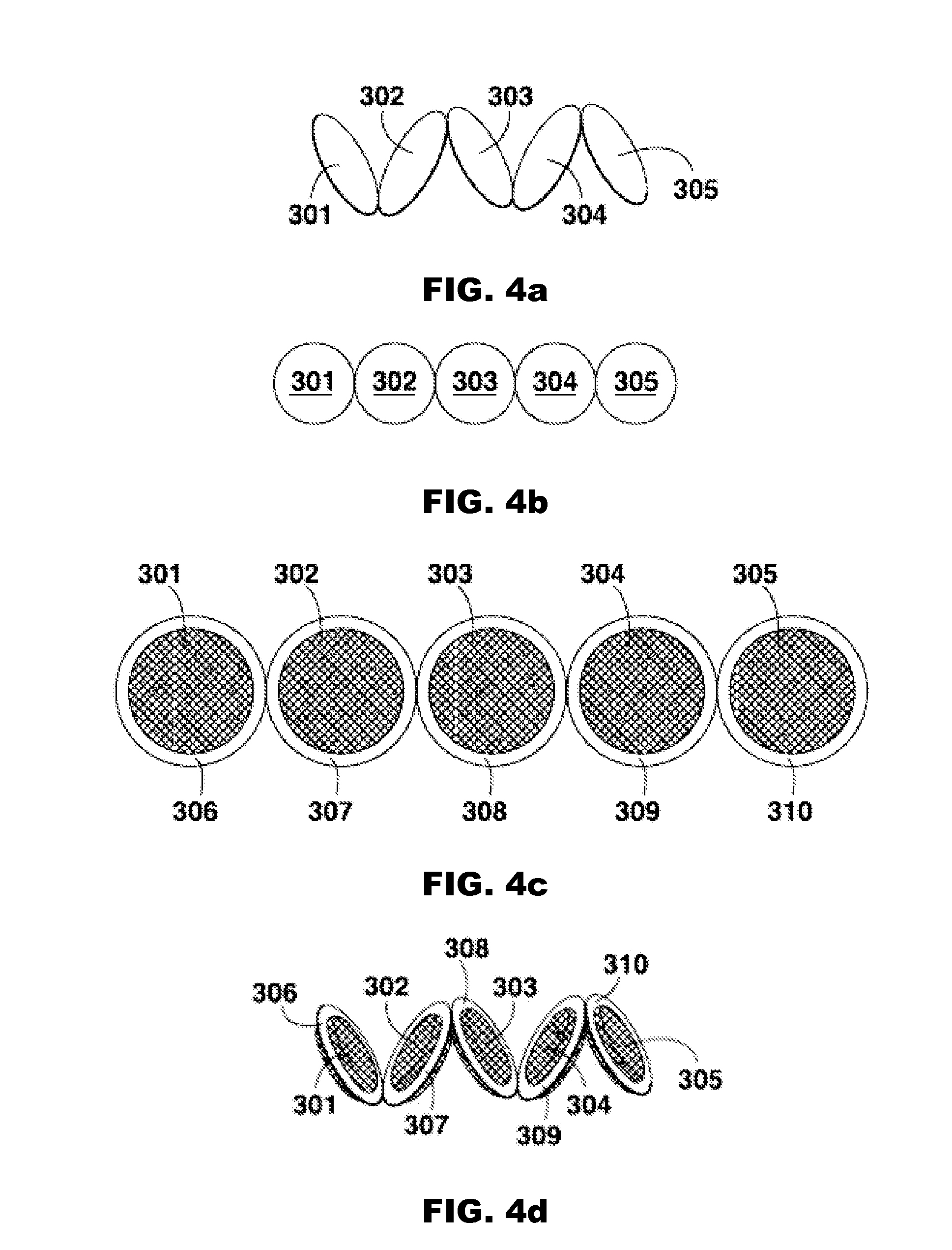
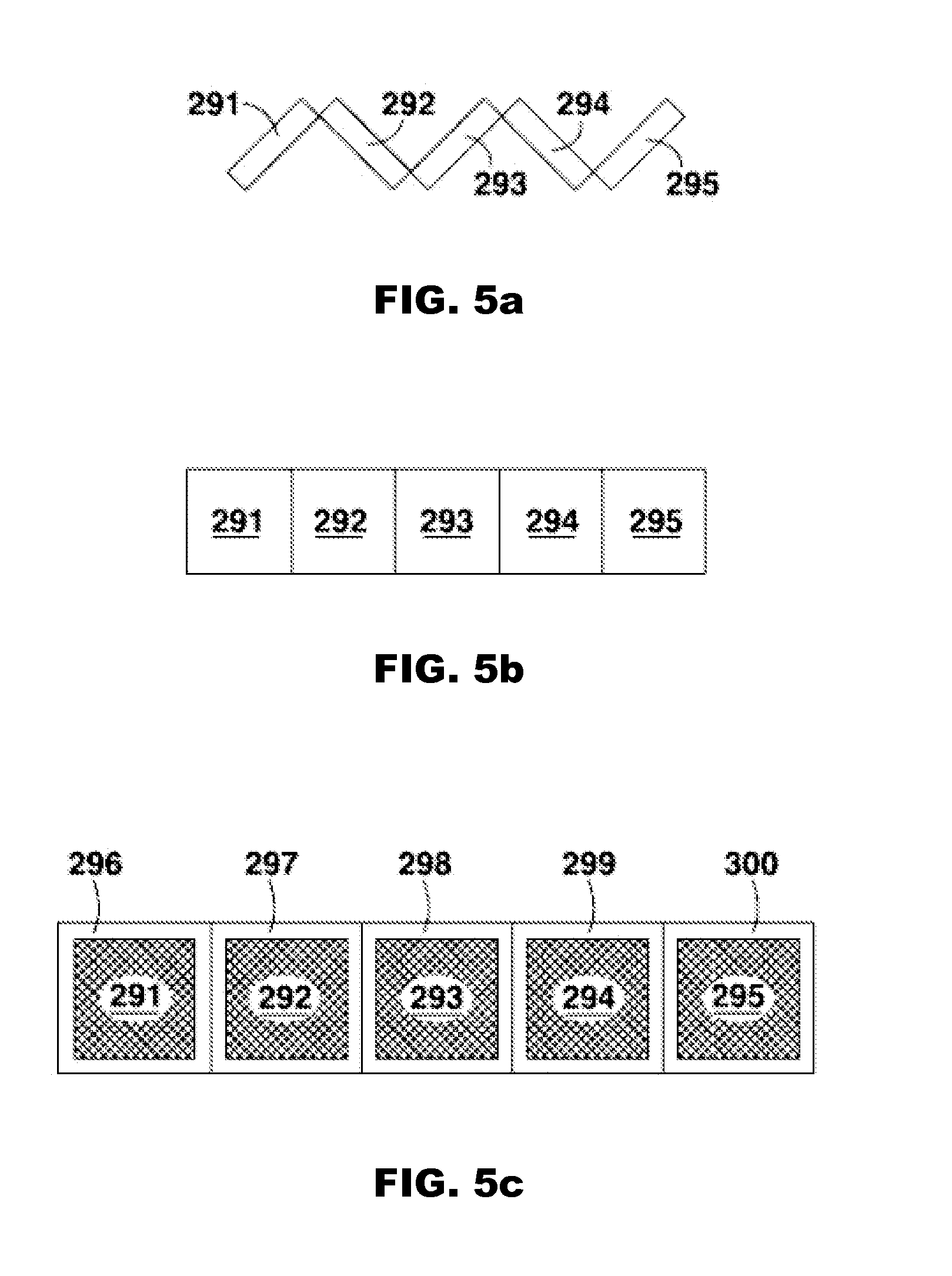
Sorbent pouch
a technology of sorbent and saline, which is applied in the direction of filtration separation, moving filter element filtering, separation process, etc., can solve the problems of high cost of sorbent dialysis system, high cost of expensive sorbent materials, waste,
- Summary
- Abstract
- Description
- Claims
- Application Information
AI Technical Summary
Benefits of technology
Problems solved by technology
Method used
Image

Examples
Embodiment Construction
[0067]Unless defined otherwise, all technical and scientific terms used herein generally have the same meaning as commonly understood by one of ordinary skill in the relevant art.
[0068]The articles “a” and “an” are used herein to refer to one or to more than one (i.e., to at least one) of the grammatical object of the article. By way of example, “an element” means one element or more than one element.
[0069]An “adhesive” is any substance known in the art for use in affixing one surface to another surface, or to seal two surfaces together.
[0070]An “annular ring” is a ring having a substantially circular shape. The cross-section of the ring may be rectangular, triangular, round, or any other known shape. The ring may be constructed of any rigid or semi-rigid material, and may be adhered to the inner surface of a sorbent pouch by any means known in the art. An annular ring may also be an “o-ring.”
[0071]The term “cartridge” refers to any container designed to contain a powder, fluid, or ...
PUM
| Property | Measurement | Unit |
|---|---|---|
| weight | aaaaa | aaaaa |
| shape | aaaaa | aaaaa |
| semi-rigid structure | aaaaa | aaaaa |
Abstract
Description
Claims
Application Information