Plunger lift assembly with an improved free piston assembly

Active Publication Date: 2016-03-03
ENDURANCE ELEVATOR SOLUTIONS LLC
View PDF3 Cites 35 Cited by
  • Summary
  • Abstract
  • Description
  • Claims
  • Application Information

AI Technical Summary

Benefits of technology

[0012]In this invention, an improved free piston assembly is used as part of a plunger lift assembly. In some preferred embodiments, the improved free piston assembly includes a sleeve member having an inner surface that is contoured such that a seat is provided for a flow restriction member. The flow restriction member is typically in the shape of sphere (referred to generically in some instances as a “ball”)

Problems solved by technology

This is in contrast to prior art devices that require latching and do n

Method used


Image

  • Plunger lift assembly with an improved free piston assembly
  • Plunger lift assembly with an improved free piston assembly
  • Plunger lift assembly with an improved free piston assembly

Examples


Embodiment Construction

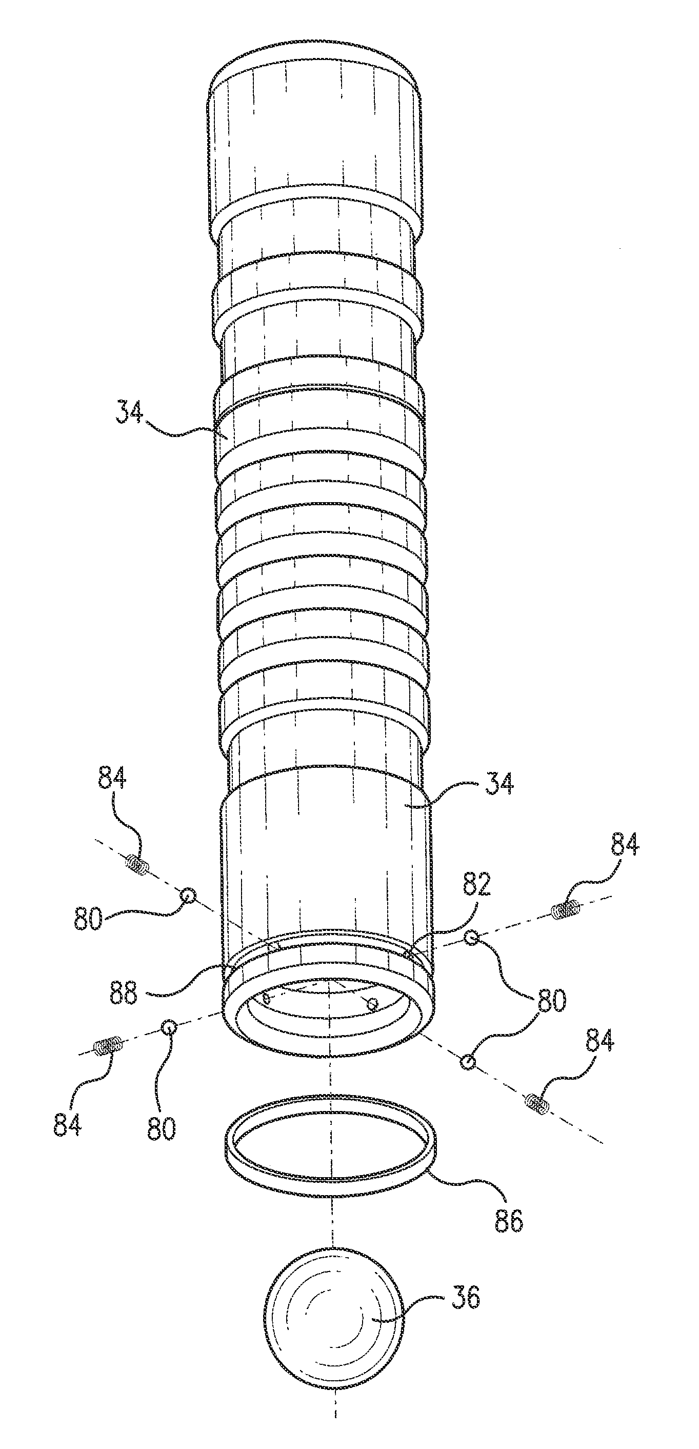
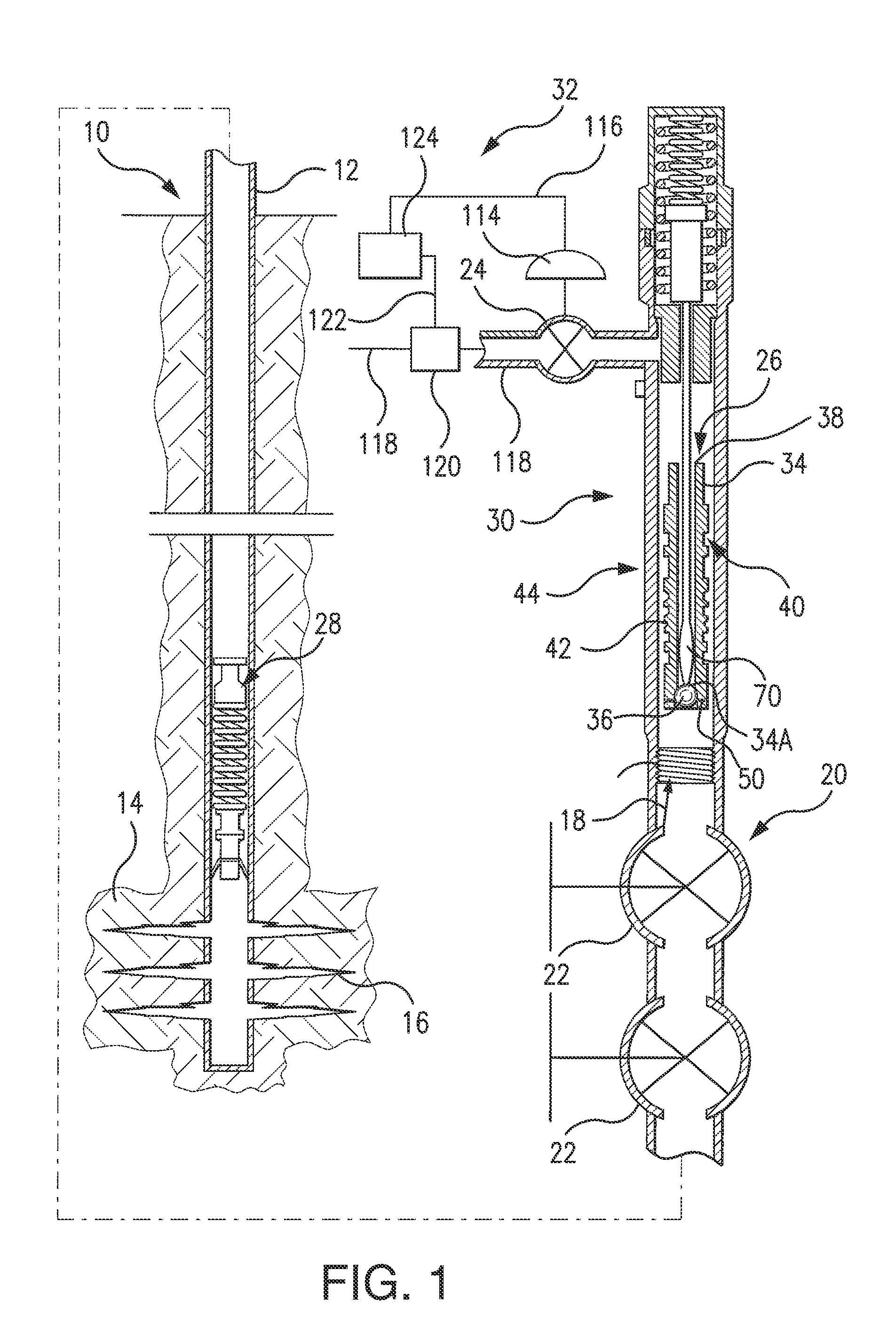
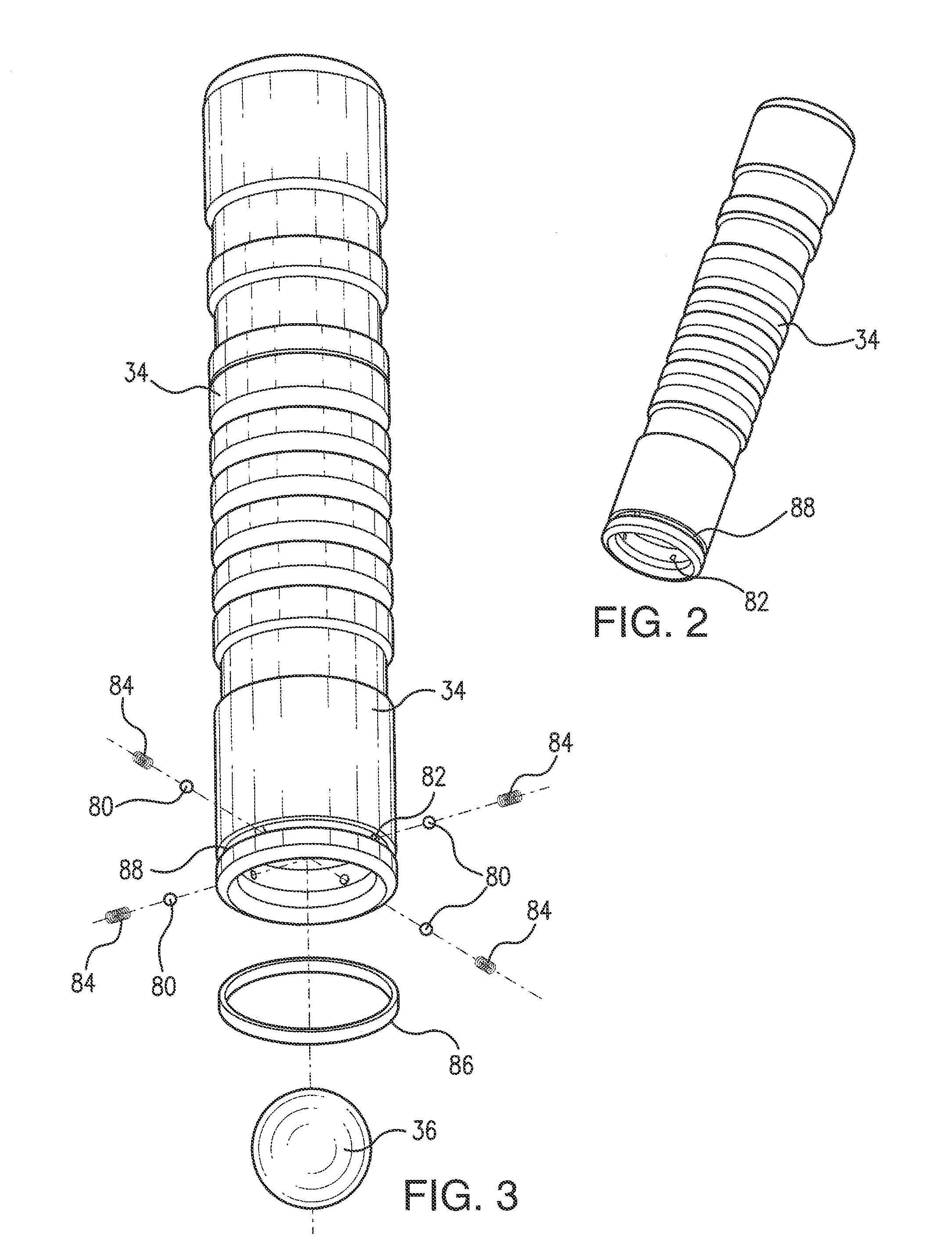
[0034]The multipart plunger embodiments shown in commonly assigned U.S. Pat. No. 6,467,541 has proven to be quite satisfactory for a wide range of applications where gas wells produce sufficient liquid that slows down gas production and ultimately kills the well. Experience and analysis resulted in two improvements being made in the operation of a multipart plunger. These improvements are disclosed in commonly assigned U.S. Pat. No. 6,719,060 and are described with more particularity below and in the specification of the U.S. Pat. No. 6,719,060 patent.

[0035]In one embodiment of the plunger lift assembly used in combination with the improved free piston assembly of this invention, the technique used to separate and hold the plunger at the surface employs moving parts to receive and cushion the impact of the plunger as it arrives at the surface but employ no moving parts to hold the plunger in the well head. A separator rod is provided which the plunger sleeve slides over, thereby dis...


PUM


Abstract

An improved free piston assembly for use in combination with a plunger lift assembly is provided. The improved free piston assembly includes a sleeve member, a flow restriction member, and retention means. In some embodiments of the invention the sleeve member has an inner surface that is contoured to provide a seat for the flow restriction member during lifting operations. The flow restriction member can be a ball held in the interior of the sleeve by retention means capable of overcoming the force of gravity but at the same time designed to release the flow restriction member when a rod of the plunger lift assembly contacts the flow restriction member. In one embodiment of the invention the retention means is a plurality of inwardly biased spring loaded held in place by a retention ring that is fittably received by a groove in the exterior surface of the sleeve. In other embodiments of the invention the retention means are in the form of a raised lip or a retention sleeve.

Description

FIELD OF INVENTION[0001]This invention relates to a plunger lift for moving liquids upwardly in a hydrocarbon well and more particularly to an improved free piston assembly that is an integral part of the plunger lift assembly.BACKGROUND OF THE INVENTION[0002]The plunger lift assembly and method for using such an assembly is disclosed in commonly assigned U.S. Pat. Nos. 6,467,541 and 6,719,060, which are incorporated herein by reference. For purposes of background and context, portions of the above patents, which have been incorporated by reference, will be repeated in this application.[0003]There are many different techniques for artificially lifting formation liquids from hydrocarbon wells. Reciprocating sucker rod pumps are the most commonly used because they are the most cost effective, all things considered, over a wide variety of applications. Other types of artificial lift include electrically driven down hole pumps, hydraulic pumps, rotating rod pumps, free pistons or plunge...

Claims


Application Information

Patent Timeline
IPC IPC(8): E21B43/12E21B34/08
CPCE21B43/123E21B2034/002E21B34/08E21B43/121F04B31/00F04B47/12
Inventor ZIMMERMAN, JR., JEFFREY, BRIAN
Owner ENDURANCE ELEVATOR SOLUTIONS LLC
Why Eureka
Try Eureka