Air-cooling-type cooler

A cooler and air-cooled technology, applied in the direction of indirect heat exchangers, heat exchanger fixation, heat sinks, etc., can solve the problem that the cooling pipes and fins are easily blocked by dust, the cooling fins have limited heat dissipation capacity, and increase maintenance Frequency and other issues, to achieve good insurance effect, convenient space collocation and layout, and optimize the installation plan

Inactive Publication Date: 2016-08-31
刘少春
View PDF8 Cites 2 Cited by
  • Summary
  • Abstract
  • Description
  • Claims
  • Application Information

AI Technical Summary

Problems solved by technology

Moreover, the heat dissipation fins or the fin pitch cannot be made very high or widened. If the heat dissipation fins are increased, the heat dissipation fins will be easily deformed, and the heat dissipation capacity of the heat dissipation fins that are too short is also limited. The height can only be within 10mm. If the fin pitch is widened, there will be a gap in the middle of the cooling tube. Since there is no cooling fin in this distance, the heat transfer rate will be affected, so the cooling fin must match the cooling tube.
It is precisely because of these factors that the entire cooler is very weak and it is difficult to resist external shocks
Moreover, due to the overall weakness, it is difficult to resist corrosion caused by environmental pollution. In addition, the small fin pitch and the flat cooling pipe and fin are very easy to be blocked by dust, which increases the frequency of maintenance and greatly reduces the service life.
When the cooler fails and cannot continue to work, it must be repaired or replaced immediately

Method used


Image

  • Air-cooling-type cooler
  • Air-cooling-type cooler
  • Air-cooling-type cooler

Examples


Embodiment 1

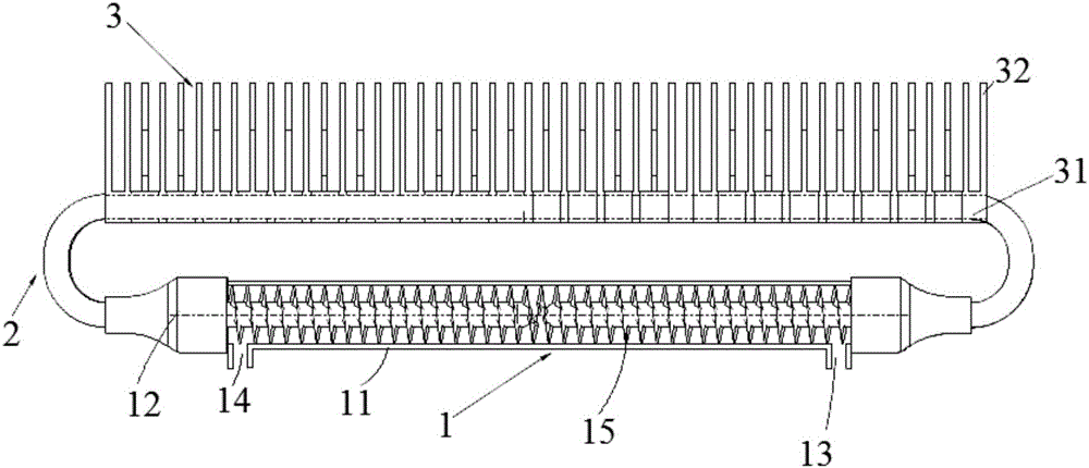
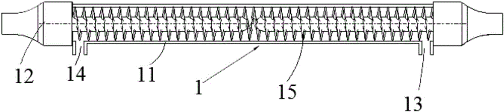
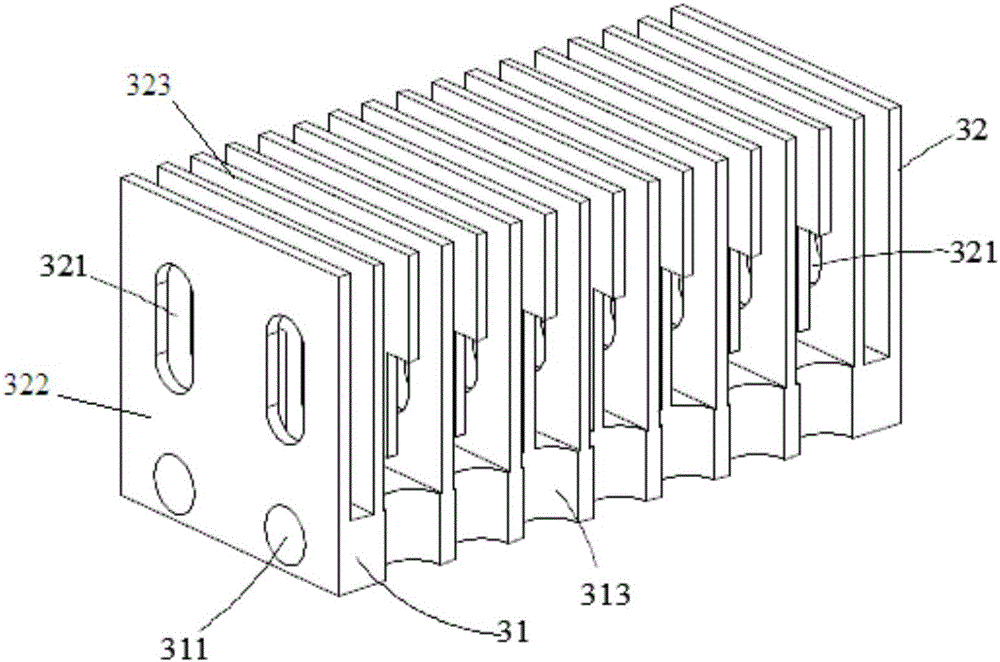
[0038] Such as Figure 1 to Figure 7 As shown, the air-cooled cooler provided in this embodiment includes an exchanger 1 , a conductor 2 and a heat dissipation group 3 , and the exchanger 1 is connected to the heat dissipation group 3 through the conductor 2 . The main feature of the present invention is to transfer energy, which can be simply understood as separating the exchanger from the heat dissipation group 3, no longer using the cooling pipe wall as the heat transfer object, but using superconducting heat pipes to separate the transfer, and then the heat dissipation group 3 dissipates heat , to achieve the purpose of cooling. During the cooling operation, the heat source fluid completes the energy exchange in the exchanger 1, and the conductor 2 transfers the energy to the heat dissipation group 3 for heat dissipation to achieve the cooling effect, thereby solving the defect of relying on the heat transfer of the tube wall, and then making the cooling tube do Relativel...

Embodiment 2

[0051] Such as Figure 8 As shown, the difference from Embodiment 1 is that the cooling group 3 is replaced by the exchanger 1 . In this embodiment, different functions can be obtained by expanding the heat dissipation end. When the heat dissipation group 3 is replaced by the exchanger 1, that is, two exchangers 1 are combined, one exchanger 1 is for cooling fluid, and the other is for heat source. The fluid thus achieves the cooling effect, and the cooling effect is superior. The biggest advantage of this structure is that the cooling section and the heat source section are completely separated, and the two different materials used in the system will not be connected to each other due to the rupture and damage of the conductor 2, which will cause the failure to expand. Because the heat source The relationship between the two substances and the cooling source are often different and incompatible or even very taboo. The coolers used by the traditional two-fluid all have the pr...


PUM


Abstract

The invention belongs to the technical filed of coolers, and particularly relates to an air-cooling-type cooler. The air-cooling-type cooler structurally comprises an exchanger, a conduction device and a heat dissipation group, wherein the exchanger is connected with the heat dissipation group through the conduction device. Compared with the prior art, the air-cooling-type cooler has the advantages that separation-type design is adopted, and the conduction device is used for conducting heat, so that the defect that heat conduction is performed relying on a pipe wall of a cooling pipe is thoroughly solved; pipe walls of any thicknesses can be designed according to needs without affecting heat exchanging efficiency, so that the problem that the cooling pipe is thin and non-corrosion-resistant, and easily leaks and the like are solved; the safety is greatly improved, and service life is greatly prolonged. The heat dissipation group is provided with a base of the own, so that fin distances, fin heights, fin thicknesses can be flexibly designed according to application environments; the air-cooling-type cooler can form good match with the environments; and the efficiency is effectively improved, and meanwhile, the application field is widened.

Description

technical field [0001] The invention belongs to the technical field of coolers, in particular to an air-cooled cooler. Background technique [0002] Air-cooled finned coolers are one of the main coolers used to dissipate heat from equipment today. The finned cooler structure is generally composed of three parts: the air inlet / liquid chamber (inlet / liquid port), heat dissipation core, air outlet / liquid chamber (air outlet / liquid port), and its working principle is: the fluid heat source enters from the inlet The cooling pipe of the heat dissipation core, the cooling pipe increases the corresponding heat dissipation area with the help of the installed fins, and achieves the purpose of heat dissipation in the way of air cross flow. The heat dissipation core of its core component is generally composed of cooling pipes and heat dissipation fins. The cross section of the cooling pipe is round or oblate and wide, and the inner groove "V" groove shape is formed inside or a pluralit...

Claims


Application Information

Patent Timeline
Patent Type & Authority Applications(China)
IPC IPC(8): F28D15/02F28F1/20
CPCF28D15/0266F28F1/20F28F2215/08F28F2275/06
Inventor 刘少春
Owner 刘少春
Why Eureka
Try Eureka