USB connector structure

a technology of usb connectors and connectors, applied in the direction of coupling devices, two-part coupling devices, electrical devices, etc., can solve the problems of reducing affecting the speed of data transmission, and consuming a considerable amount of solventing procedure during the manufacturing of usb connectors, so as to shorten the prior usb connector manufacturing process , convenient and efficient

Inactive Publication Date: 2014-12-02
ZK TEK TECH
View PDF5 Cites 2 Cited by
  • Summary
  • Abstract
  • Description
  • Claims
  • Application Information

AI Technical Summary

Benefits of technology

[0008]The primary object of the present invention is to provide a USB connector structure, comprising a base, a main structure, a plural of pins and a fixing structure, wherein both the main structure and the fixing structure are configured over the base and are formed as a whole body by firmly hooked and fastened with each other, and one side of those said pins are configured as bending ends which extend outside of the main structure and provide electric contact with those conducting pads laid on the base correspondingly. Therefore, the present invention enables those pin applied in the USB connector structure a convenient assembly free from traditional soldering procedure, and provides a more convenient and efficient method to shorten prior USB connector manufacturing process.
[0009]Another object of the present invention is to provide a USB connector structure, wherein both the fixing structure and the main structure are configured as various joint combinations which enable a strong fastening assembly between each part. And, the clipping arm is configured either in the main structure or the fixing structure to provide a fastening function with the base. Thus, the present invention provides a better and simple joint structure.
[0010]And, one more object of the present invention is to provide a USB connector structure, wherein the bottom side of the fixing structure is further configured with a step rabbet which provides a pushing effect and accommodates those pins extended outside the main structure to enable the curve part of each bending edge having a tight and better electric contact with those conducting pads laid on the base correspondingly. This joint structure can reduce transmission error or hardware damage caused by frequent plug-in and pull-out or vibration. Obviously, the present invention does not only provide a useful structural combination for the manufacturer, but also enhance the transmission function and safety for the ordinary USB interface user.
[0011]By above-mentioned description, the present invention is applicable to provide a USB connector structure with a more efficient manufacturing process and a more reliable hardware structure. Above all, the present invention is assembled free from soldering process which provides a convenient and efficient method to shorten prior USB connector manufacturing process.

Problems solved by technology

The soldering procedure takes a considerable time consuming during the USB connector manufacturing.
There are nine pins adopted in standard USB 3.0 connectors and the soldered tin might lead to an inferior conducting effect after many times plug-in and pull-out.
And, it also reduces the speed of data transmission and, furthermore, data or memory is damaged and can not be retrieved.

Method used


Image

  • USB connector structure
  • USB connector structure
  • USB connector structure

Examples


Embodiment Construction

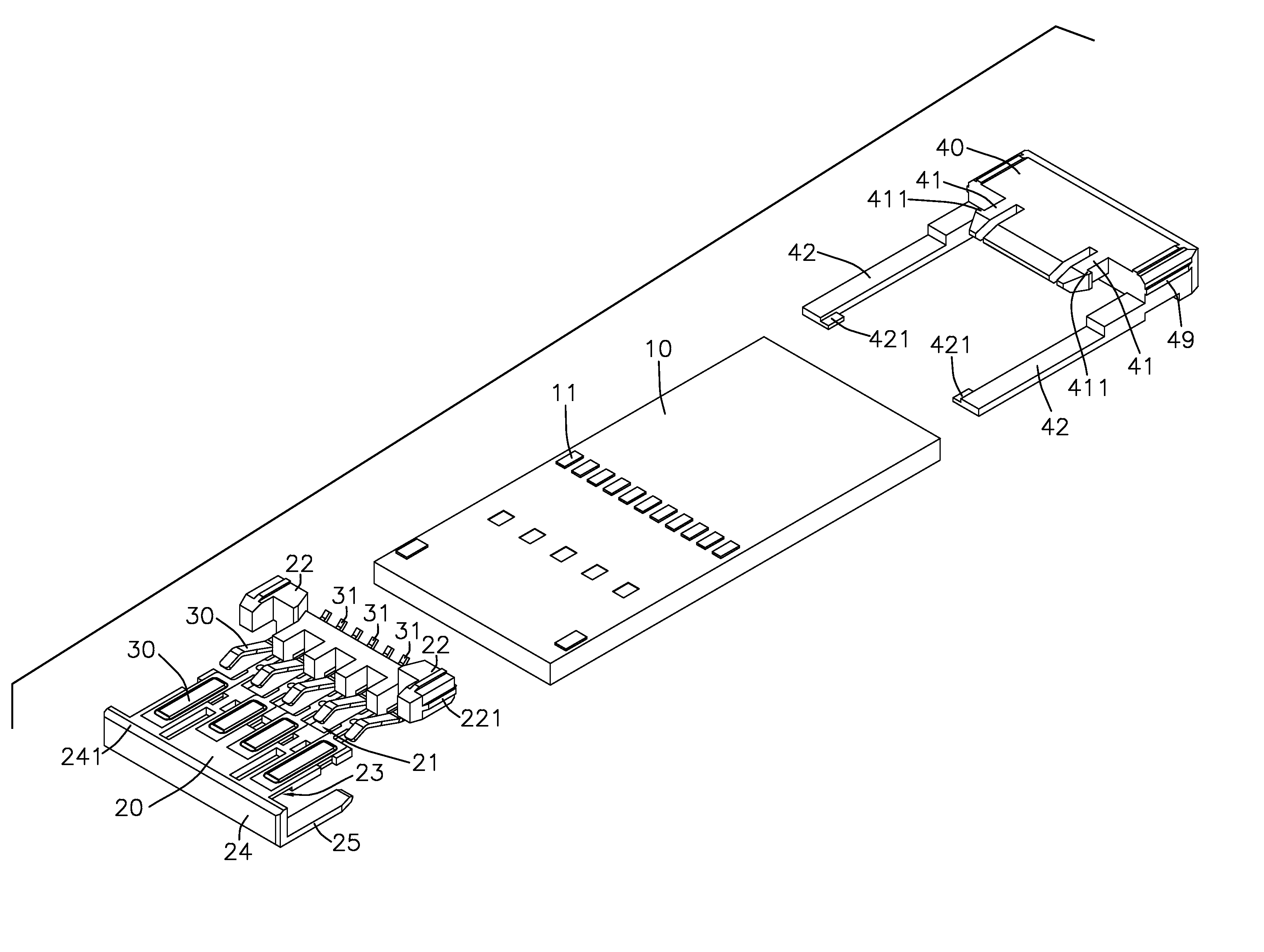
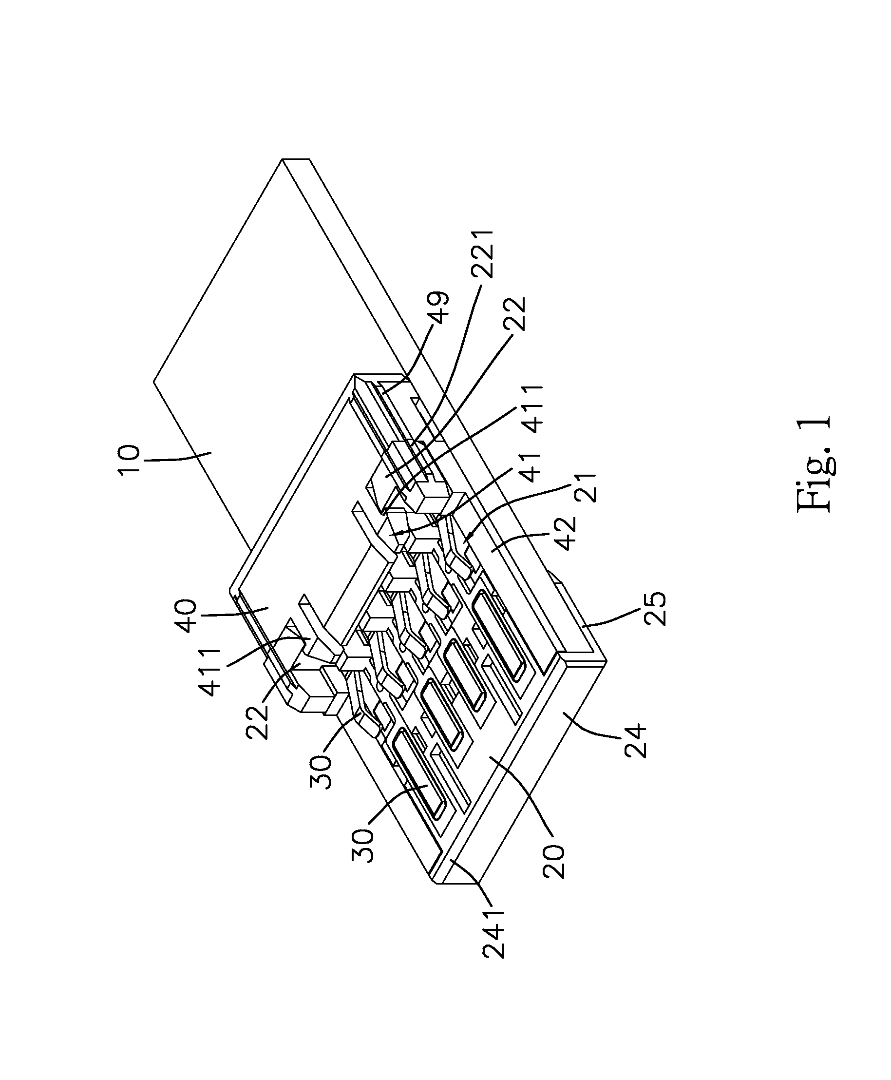
[0030]Referring to FIGS. 1˜14, the present invention relates to a USB connector structure and comprises a base 10, a main structure 20, a plural of pins 30 and a fixing structure 40, wherein a plural of conducting pads 11 are laid on top of base 10 and the main structure 20 is configured over the base 10. The main structure 20 is configured with pin rabbets 21 to have one side accommodate pins 30 respectively. And, the other side of pins 30, passing through the main structure 20, are configured as bending ends 31 which extend outside of the main structure 20 and provide electric contact with those conducting pads 11 laid on the base correspondingly. The fixing structure 40 is also configured over the base 10. And, the fixing structure 40 is formed as a whole body with the main structure 20 by firmly hooked and fastened with each other. The bottom side of the fixing structure 40 is further configured with a step rabbet 48 which provides a pushing effect and accommodates those pins 30...


PUM


Abstract

A USB connector structure, configured with a combination structure of a base, a main structure, a plural of pins and a fixing structure, to enable said plural pins to be configured on the conducting pads without soldering process and to provide a convenient assembly by firmly hooking and fastening both the main structure and the fixing structure over the base. And, the present invention can be applied in various USB connectors or similar connecting structure.

Description

BACKGROUND OF THE INVENTION[0001]1. Field of the Invention[0002]The present invention relates to a USB connector structure, comprising a base, a main structure, a plural of pins and a fixing structure, wherein the main structure and the fixing structure are configured over the base and are formed as a whole body by firmly hooked with each other, and one side of those pins are configured as bending ends which extend outside of the main structure and provide electric contact with those conducting pads laid on the base correspondingly. Therefore, the present invention enables those pin applied in the USB connector structure a convenient assembly without traditional soldering procedure, and provides a more convenient and efficient method to shorten prior USB connector manufacturing process.[0003]2. Description of Prior Art[0004]The USB connectors had been adopted as a standard port to act as a transmission interface between the computer and external peripherals. Especially, USB connecto...

Claims


Application Information

Patent Timeline
Patent Type & Authority Patents(United States)
IPC IPC(8): H01R24/00H01R24/64
CPCH01R13/506H01R24/62H01R12/714H01R13/6658H01R24/64
Inventor CHAN, YI CHIA
Owner ZK TEK TECH
Why Eureka
Try Eureka