

Variable dose inhalation device
a technology of inhalation device and varying dose, which is applied in the field of inhalation device, can solve the problems of large clusters making it to the deep lungs then decreasing, uncertainty, and lower percentage of drug being available to the patient for absorption, so as to facilitate the administration of varying doses and improve compliance and efficacy.
- Summary
- Abstract
- Description
- Claims
- Application Information
AI Technical Summary
Benefits of technology
Problems solved by technology
Method used
Image

Examples
first embodiment
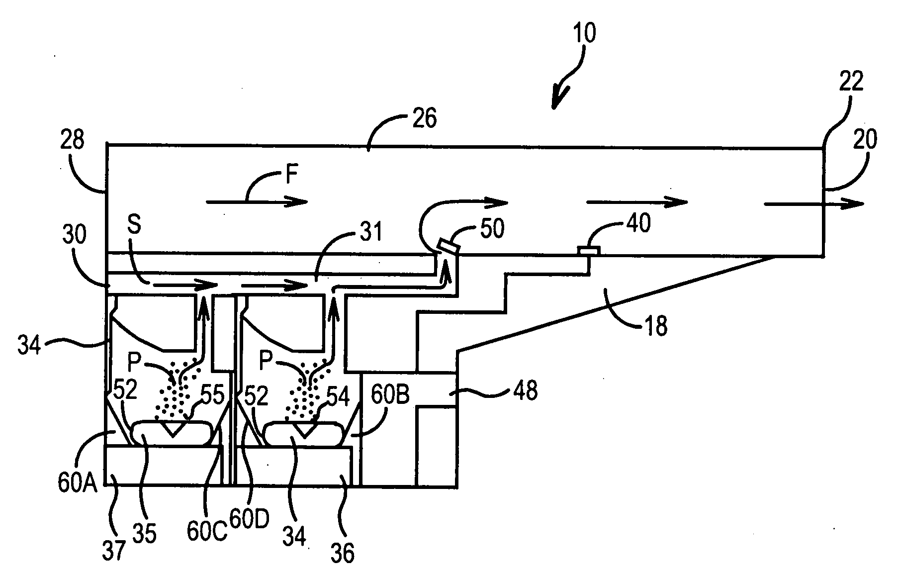
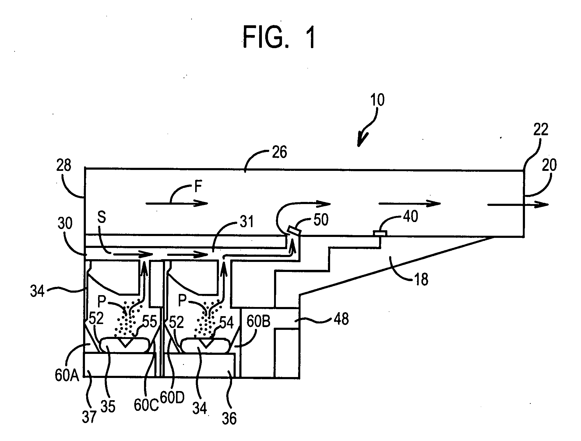
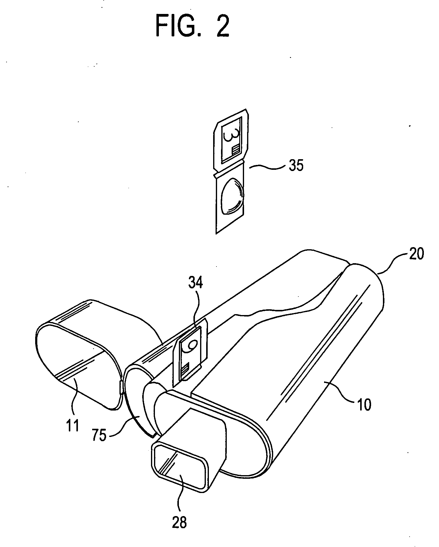
[0049]FIGS. 1-3 illustrate the present invention. An inhaler 10 includes a hard plastic or metal housing 18 having a generally L-shaped longitudinal cross-section with a mouthpiece cover 11. Housing 18 includes four air flow openings 20, 28, 30, and 32. Inhaler 10 includes a main air flow passage 26 which extends the length of the housing 18 from the front 22 (at opening 20) to the rear 24 thereof (at opening 28) and has a generally square-shaped transverse cross-section, so as to permit air flow through (denoted by arrow F in FIG. 3).
[0050]Optional secondary air conduit 31 is generally L-shaped and runs longitudinally from opening 30 in the rear 24 surface of the housing 18 to main passage 26. One-way flow valve 50 is mounted to the inner surface of the main passage 26 via a spring-biased hinge mechanism (not shown), which is adapted to cause the valve 50 to completely block air flow S through the conduit 31 to the main passage 26 when the pressure of the air flow F in the main pas...
embodiment 100
[0057]A second preferred embodiment 100 of the present invention is shown in FIG. 4. In this embodiment, the inhaler 100 only contains one powder dispensing chamber 102. Chamber 102 contains two vibration mechanisms 104, 106, which allow two blister packs 34, 35 to be placed on the seating of vibration mechanisms 104, 106. The air flow P including the drug from both cartridges 34, 35 flow through passageway 108 through the conduit 31 to the main passage 26.
[0058]FIG. 5-6 illustrate a third embodiment 202 of the present invention. In this embodiment, the inhaler is designed to accommodate a pair of cartridge strips only one of which 214 is shown, that are inserted into a slot (not shown) in the back 204 of the inhaler 202. A mouthpiece cover 206 (shown covered) is hingedly rotatably attached over a mouthpiece (not shown) at the front of the inhaler. Each cartridge strip carries a plurality of blister packs 34. Preferably, all of the blister packs 34 on a particular strip contain simi...
fifth embodiment
[0062]the present invention uses a spool or carousel 402 to protect blisters 90 before delivery, as illustrated in FIG. 10. In use, carousel 402 is mounted to a slot 404 in the inhaler 400. The carousel 402 is rotated to deliver a blister 90 to opening 410. The blisters 90 then can drop from the slot 404 through the opening 410 into the inhaler where they can be opened and processed as before. The blisters contained in the spool carousel each contains the same dosage of a drug. Other packaging techniques and structures for protecting blisters are illustrated in FIGS. 11-12.
[0063]Referring now to FIGS. 13A and 13B, an embodiment of the present invention includes resonant cavity 500 capable of aerosolizing and ejecting the drug substance from drug ejection apertures 510, upon actuation by the vibrator 530, such a piezo actuator or transducer, which is coupled to resonant cavity 500. A dose pack or blister delivery window 520 is provided for depositing variable quantity of drug substan...
PUM
 Abstract
Description
Claims
Application Information