
Injector device for placing a subcutaneous infusion set

Active Publication Date: 2005-02-24
UNOMEDICAL AS
View PDF98 Cites 141 Cited by
  • Summary
  • Abstract
  • Description
  • Claims
  • Application Information

AI Technical Summary

Benefits of technology

[0006] In accordance with the invention, an injector device has a plunger with a medical needle which may be hollow to allow for discharge of medication when priming the infusion set, and which is adapted for the quick and easy transcutaneous placement through the skin of a patient of the cannula of a subcutaneous infusion set, the insertion needle extending through the infusion set and protruding from the end of the cannula. The injector device is designed to place the cannula with the insertion needle extending therethrough, preferably with a controlled force and speed of insertion, to ensure proper needle placement with minimal patient discomfort The injector device may also allow placement of the insertion needle through the skin at a selected insertion angle. After priming and placement of the infusion set the injector device is removed and delivery of medication is initiated.
[0007] Preferably, the injector device is provided to the patient as a sterile sealed, single use assembly including a subcutaneous infusion set with a housing already mounted on the insertion needle of the injector device, thereby reducing the number of components to be handled by the patient prior to the placement of the subcutaneous infusion set. The injector device assembly may be designed such that no further packaging is required leading to substantial cost reductions.
[0009] Preferably, the injector comprises a spring-loaded plunger having a head for receiving the infusion set in a position with the insertion needle projecting outwardly for transcutaneous placement through the skin of a patient. A front end of the housing is designed for being pressed against the skin of a patient, at a selected needle insertion site; and in an orientation with the needle disposed at a correct or desired insertion angle. A trigger member is operable to release the plunger and thereby permit the drive spring to carry the infusion set toward the patient's skin with a controlled force and speed, resulting in proper transcutaneous placement of the insertion needle with minimal patient discomfort.

Problems solved by technology

Some patients are reluctant or hesitant to pierce their own skin with a medical needle, and thus encounter difficulties in correct needle placement for proper administration of the medication.
Such difficulties can be attributable to insufficient manual skill to achieve proper needle placement or alternately to anxiety associated with anticipated discomfort as the needle pierces the skin.
This problem can be especially significant with medications delivered via a subcutaneous infusion set, since incorrect placement can cause kinking of the cannula and resultant obstruction of medication flow to the patient Cannula kinking can be due to infusion set placement at an incorrect angle relative to the patient's skin, and / or needle placement with an incorrect force and speed of insertion.

Method used


Image

  • Injector device for placing a subcutaneous infusion set
  • Injector device for placing a subcutaneous infusion set
  • Injector device for placing a subcutaneous infusion set

Examples


Embodiment Construction

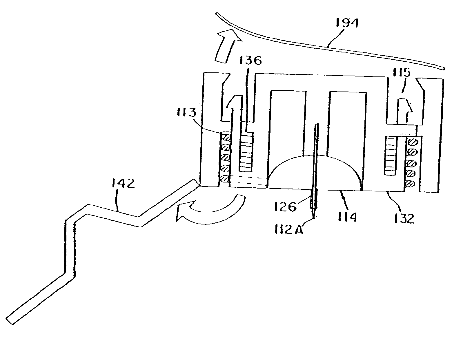
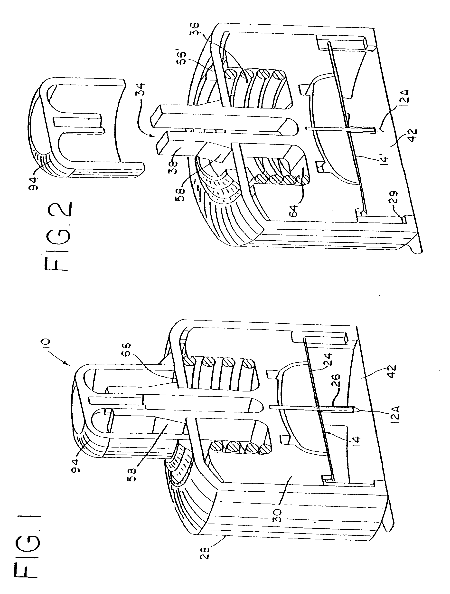
[0037] An injector device shown schematically in FIG. 1 by the reference numeral 10 is provided for quick and easy placement of a subcutaneous infusion set 14, and may then be discarded safely. The infusion set 14 with a cannula 26 extending therefrom is shown schematically only.

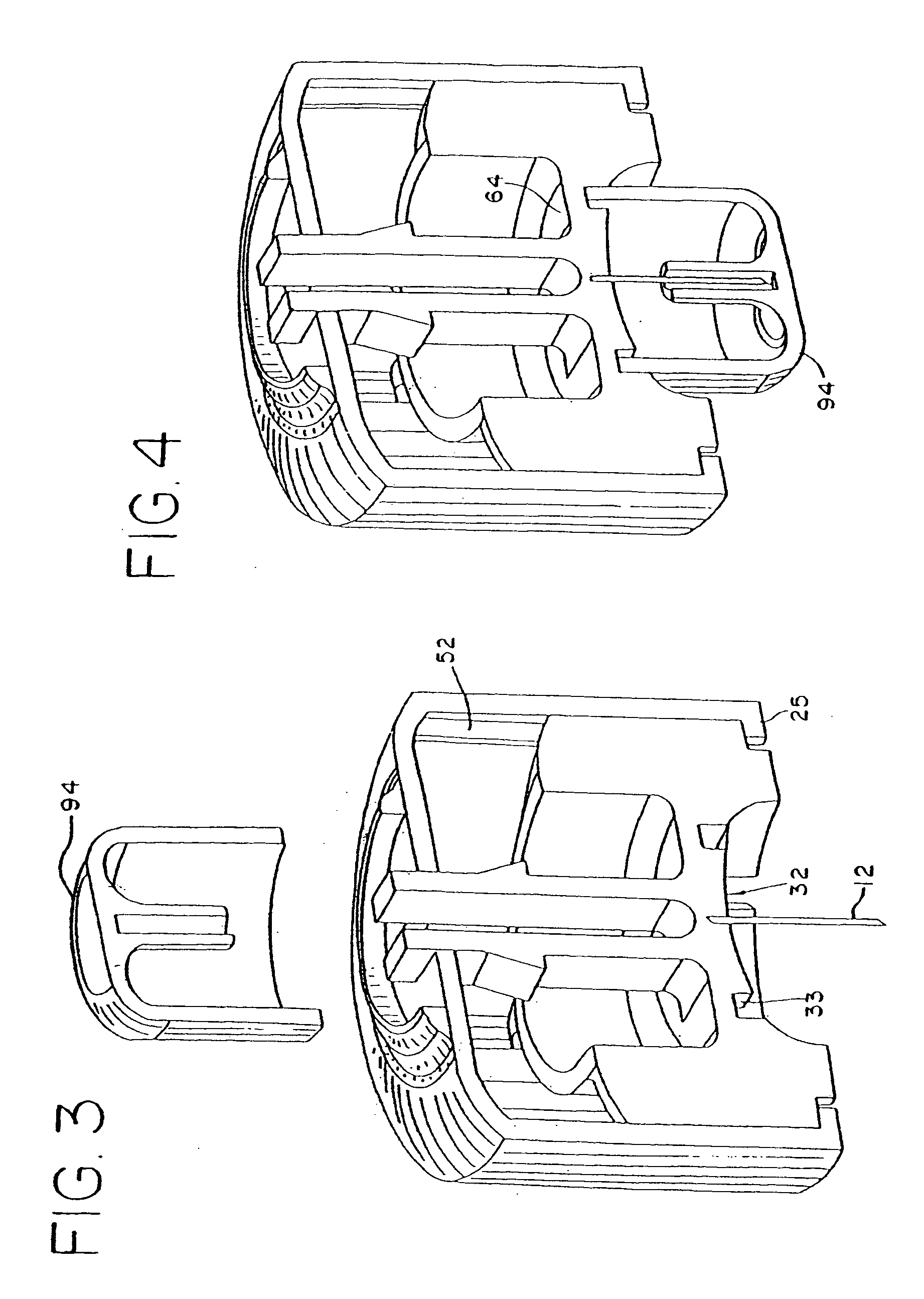
[0038] The injector device 10 includes a plunger 30 having thereon a medical insertion needle 12 with a pointed end 12A. The plunger 30 is arranged for longitudinal sliding movement within a device housing 28 between a forward advanced position (FIG. 3 and 4) and a rearward retracted position (FIG. 1 and 2). The device housing 28 may have a circular, square or any desired cross-sectional shape. The device housing 28 and the plunger 30 are preferably formed of a plastics material in a moulding process.

[0039] The infusion set 14 is used to infuse medical fluids such as insulin to a patient, and generally includes a housing with an internal chamber (not shown) that receives medication via infusion tubing. An ...


PUM


Abstract

An injector device assembly and a method for making an injector device assembly are provided. The injector assembly includes a sterile insertion set with a housing and a hollow cannula and a device housing. A plunger is slidably received within the device housing for movement between an advanced position and a retracted position wherein the cannula is transcutaneously placed upon movement of the plunger from the advanced position to the retracted position. The device housing has a forward end defining a surface of placement against the skin of a patient with the device housing in a predetermined orientation relative to the patient's skin. The injector device assembly includes a spring for urging the plunger toward the advanced position and a releasable cover member covering the forward end. The cover member and the device housing assure sterile conditions of the insertion set within the device housing prior to removal of the cover member.

Description

BACKGROUND OF THE INVENTION [0001] This invention relates generally to an improved injector device for the placement of a subcutaneous infusion set on a patient. Examples of injector devices for the placement of a subcutaneous infusion set are disclosed in U.S. Pat. No. 6,093,172, U.S. Pat. No. 5,851,197 and WO 99 / 33504, incorporated by reference herein. [0002] Medical needles are widely used in the course of patient treatment, particularly for delivery of selected medications. In one form, hollow hypodermic needles are employed for transcutaneous delivery of the medication from a syringe or the like, see U.S. Pat. No. 5,665,071. In another, as shown in U.S. Pat. No. 5,591,188 incorporated herein by reference, an insertion needle used in conjunction with an injector device is employed for transcutaneous placement of a soft and relatively flexible tubular cannula, followed by removal of the insertion needle and subsequent infusion of medical fluid to the patient through the cannula. ...

Claims


Application Information

Patent Timeline
IPC IPC(8): A61M5/20A61M5/158A61M25/06
CPCA61M5/158A61M2005/1585A61M2005/1581A61M25/0631
Inventor MOGENSEN, LASSE WESSELTOFTKORNERUP, GRETEGORANSSON, MAGNUS WALTER
Owner UNOMEDICAL AS
Learn More