Display module with heat dissipation structure and handheld device thereof

a technology of heat dissipation structure and display module, which is applied in the direction of electrical apparatus construction details, instruments, substation equipment, etc., can solve the problems of failure inability to uniformly dissipate heat in time, and deterioration of the execution efficiency of the electronic components of the display module, so as to achieve rapid and uniform heat dissipation and heat dissipation structure. , the effect of dissipation

Active Publication Date: 2016-05-12
ASIA VITAL COMPONENTS SHENZHEN CO LTD
View PDF1 Cites 12 Cited by
  • Summary
  • Abstract
  • Description
  • Claims
  • Application Information

AI Technical Summary

Benefits of technology

[0006]It is therefore a primary object of the present invention to provide a display module with heat dissipation structure. The display module has a vapor chamber to replace the back frame of the conventional display module. The vapor chamber can absorb the heat generated by electronic components and quickly and uniformly spread the heat to dissipate the heat.
[0007]It is a further object of the present invention to provide a handheld device including a display module with heat dissipation structure. The display module has a vapor chamber to replace the back frame of the conventional display module. The vapor chamber can absorb the heat generated by electronic components and quickly and uniformly spread the heat to dissipate the heat.
[0008]To achieve the above and other objects, the display module with heat dissipation structure of the present invention includes a touch display panel and a vapor chamber. The touch display panel includes a touch panel and a display panel. The touch panel has a touch face and a bottom face opposite to the touch face. The bottom face of the touch panel is connected with one face of the display panel. The touch panel is positioned on upper side of the display panel. The vapor chamber has a first side and a second side opposite to the first side. The first side of the vapor chamber is attached to the other face of the display panel. The vapor chamber serves to support the touch panel and the display panel. Moreover, the vapor chamber serves to absorb the heat generated by the electronic component and quickly and uniformly spread the heat to dissipate the heat to effectively achieve a heat spreading effect.
[0009]The handheld device of the present invention includes a display module, an electronic component assembly and a frame body. The display module includes a touch display panel and a vapor chamber. The touch display panel includes a touch panel and a display panel. The display panel is disposed between the touch panel and the vapor chamber. The touch panel has a touch face and a bottom face opposite to the touch face. The bottom face of the touch panel is attached to one face of the display panel. The touch panel is positioned on upper side of the display panel. The vapor chamber has a first side and a second side opposite to the first side. The first side of the vapor chamber is attached to the other face of the display panel. One side of the electronic component assembly is attached to the second side of the vapor chamber. The frame body has a receiving space. One side of the frame body is recessed to form the receiving space for receiving the electronic component assembly and the display module. The other side of the electronic component assembly is attached to a bottom side of the receiving space. The vapor chamber serves to support the touch panel and the display panel. Moreover, the vapor chamber serves to absorb the heat generated by the electronic component and quickly and uniformly spread the heat to dissipate the heat to effectively achieve a heat spreading effect. Moreover, a user can hold and use the handheld device more comfortably.

Problems solved by technology

When the above electronic components (such as the CPU and the GPU) and the display module generate heat, it often takes place that the heat cannot be uniformly dissipated in time.
This will lead to deterioration of the execution efficiency of the electronic components in the handheld device or even cause failure of the handheld device.
At this time, in the case that the heat continuously locally accumulates inside and around the electronic components themselves and is not quickly and uniformly dissipated, the user's hand will feel uncomfortable due to the heat.

Method used


Image

  • Display module with heat dissipation structure and handheld device thereof
  • Display module with heat dissipation structure and handheld device thereof
  • Display module with heat dissipation structure and handheld device thereof

Examples


Embodiment Construction

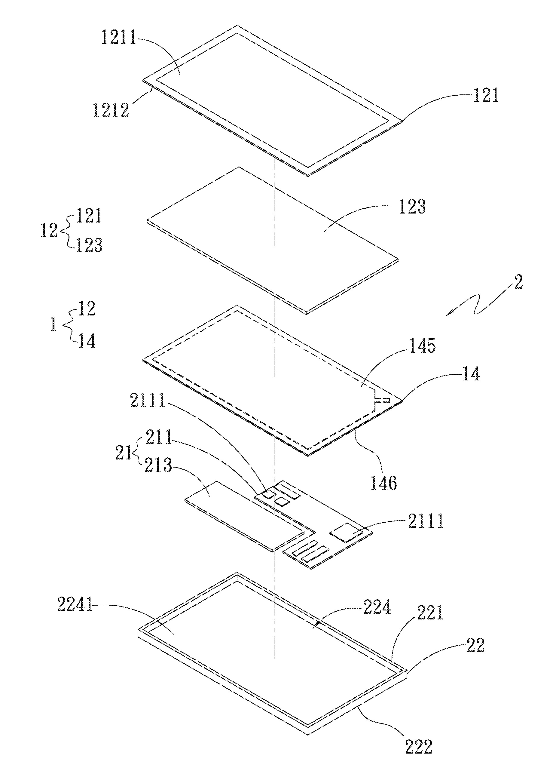
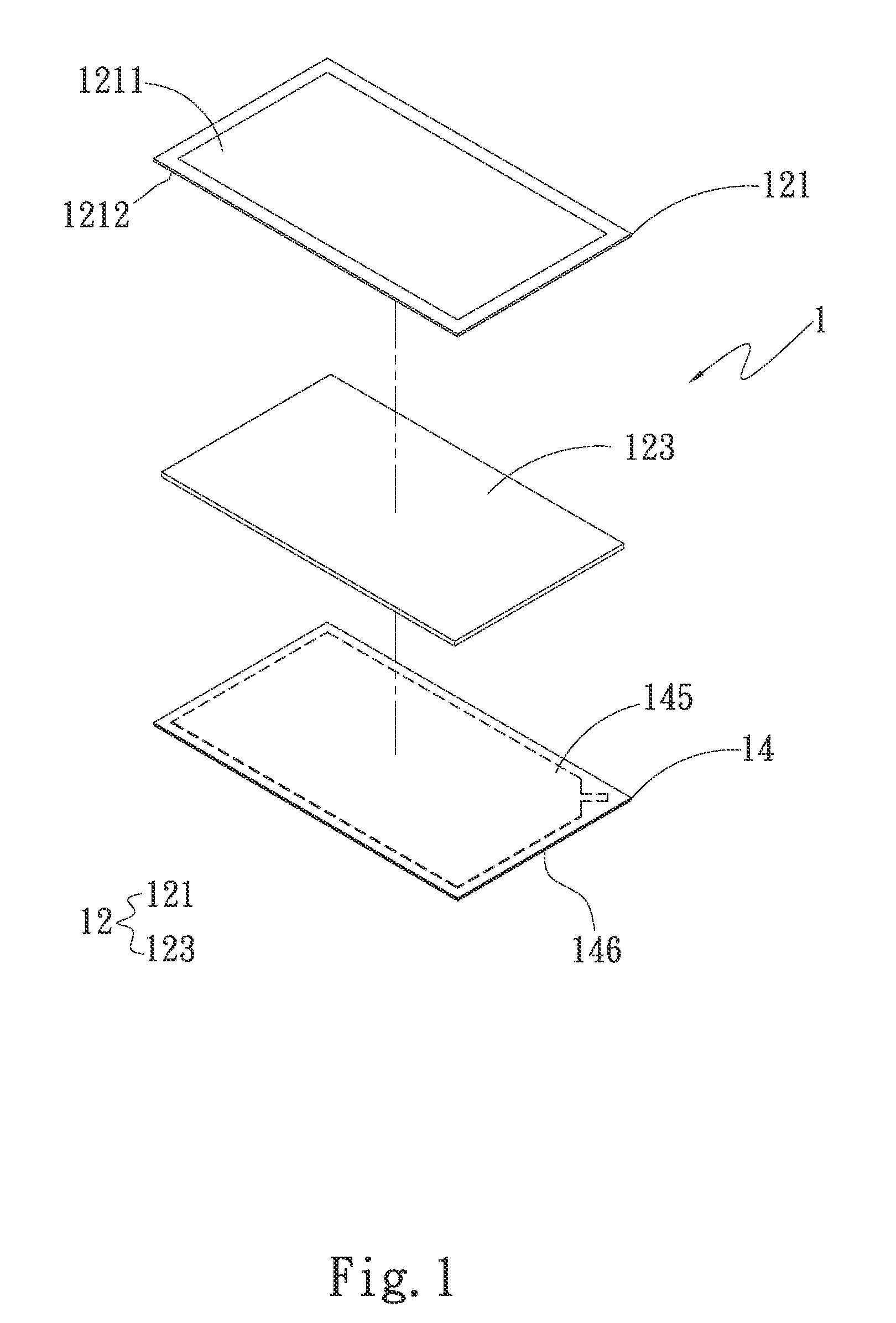
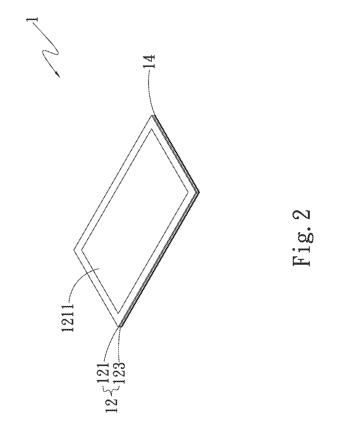
[0019]Please refer to FIGS. 1 and 2 and supplementally to FIGS. 3A and 3B. FIG. 1 is a perspective exploded view of a first embodiment of the present invention. FIG. 2 is a perspective assembled view of the first embodiment of the present invention. FIG. 3A is a sectional assembled view of the first embodiment of the present invention. FIG. 3B is a sectional exploded view of the first embodiment of the present invention. According to the first embodiment, the display module 1 with heat dissipation structure of the present invention includes a touch display panel 12 and a vapor chamber 14. The touch display panel 12 includes a touch panel 121 and a display panel 123. The touch panel 121 has a touch face 1211 and a bottom face 1212 opposite to the touch face 1211. The bottom face 1212 of the touch panel 121 is assembled with one face of the display panel 123 to form the touch display panel 12. The touch panel 121 is positioned on upper side of the display panel 123. In other words, th...


PUM


Abstract

A display module with heat dissipation structure and a handheld device thereof. The display module includes a touch panel, a display panel and a vapor chamber. One face of the display panel is correspondingly attached to the touch panel, while the other face of the display panel is correspondingly attached to the vapor chamber. The vapor chamber serves to support the touch panel and the display panel. Moreover, the vapor chamber serves to absorb the heat generated by the electronic component and quickly and uniformly spread the heat to dissipate the heat to achieve a heat spreading effect.

Description

BACKGROUND OF THE INVENTION[0001]1. Field of the Invention[0002]The present invention relates generally to a display module with heat dissipation structure and a handheld device thereof. The display module has a vapor chamber to replace the back frame of the conventional display module. The vapor chamber can absorb the heat generated by electronic components and quickly and uniformly spread the heat to dissipate the heat.[0003]2. Description of the Related Art[0004]Currently, there are various mobile devices such as tablets and intelligent mobile phones. The internal calculation execution units of the mobile devices have higher and higher operation speed. As a result, the heat generated by these units is greatly increased. In consideration of convenient carriage, these mobile devices have become thinner and thinner. With an intelligent mobile phone taken as an example, the conventional intelligent mobile phone includes a display module, a circuit board, a battery and a frame body. T...

Claims


Application Information

Patent Timeline
Patent Type & Authority Applications(United States)
IPC IPC(8): H05K7/20G06F3/041
CPCG06F3/041H05K7/20336H04M1/0266G06F1/1601G06F1/1643G06F3/0412
Inventor WU, CHUN-MING
Owner ASIA VITAL COMPONENTS SHENZHEN CO LTD
Why Eureka
Try Eureka