Heat dissipation structure for electric circuit device

a technology of electric circuit device and heat dissipation structure, which is applied in the direction of semiconductor devices, semiconductor/solid-state device details, electrical apparatus, etc., can solve the problems of difficult mass production, fragile surface of the swirl layer, and difficult contact with the adherend, so as to maintain the heat dissipation structure, excellent heat dissipation performance and mass-productivity

Active Publication Date: 2020-04-07
DENKA CO LTD
View PDF13 Cites 1 Cited by
  • Summary
  • Abstract
  • Description
  • Claims
  • Application Information

AI Technical Summary

Benefits of technology

[0025]According to an embodiment of the present invention, a ceramic-resin composite can be used as a thermal conductive member and arranged between a heatsink of a heat generator and a cooler. Thus an embodiment of the present invention can provide a heat dissipation structure for an electric circuit device, excellent in both heat dissipation performance and mass-productivity. Therefore, another embodiment of the present invention can also provide an electric circuit device which thermally protects itself and maintains its electric performance.

Problems solved by technology

However, the structure of Patent Document 3 has introduced a certain drawback that the whisker layer is fragile and the structure is difficult to mass-produce.
However, since the ceramic material is rigid and has the solid surface, it is difficult to contact with an adherend.
Even if the ceramic material is located, as a thermal conductive member, between a heatsink and a cooler and they are compressed together to adhere each other, there are air gaps at their interfaces, and the gaps spoil the heat conductivity.

Method used


Image

  • Heat dissipation structure for electric circuit device

Examples


example 1

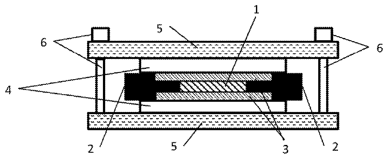
[0056]The electric circuit device A and thermal conductive member B (boron nitride-resin composite sheet) were piled up such that their center lines were overlapped and the 35 mm side of the heatsink and the 45 mm side of thermal conductive member B were arranged in parallel. Layers of thermal conductive member B were put on both the upper and lower heatsinks of electric circuit device A, respectively. They were adhered by a press machine at 10 MPa and 200 degrees C. for 24 hours. Then two coolers D were put on both the upper and lower surfaces, respectively, such that the center lines of thermal conductive member B and cooler D were overlapped and the 45 mm side of thermal conductive member B and the 50 mm side of cooler D were arranged in parallel to obtain a heat dissipation structure according to Example 1. A fastening member was attached at the four corners of the two coolers to apply the compressive load of 10 MPa evenly on the layered surface.

Evaluation of Thermal Properties ...

example 2

[0058]The same process as Example 1 was carried out except that layers of thermal grease C were provided at the interfaces between the heatsinks and thermal conductive members B. The thermal grease C layers had the thickness of 20 microns. The thermal resistance was measured for Example 2 as the same as Example 1. The result is shown in Table 2. The thermal grease C layers were formed by a screen printer.

example 3

[0059]The same process as Example 1 was carried out except that layers of thermal grease C were provided at the interfaces between the thermal conductive members B and the coolers D. The thermal grease C layers had the thickness of 20 microns. The thermal resistance was measured for Example 3 as the same as Example 1. The result is shown in Table 2.


PUM

PropertyMeasurementUnit
mean particle diameteraaaaaaaaaa
aspect ratioaaaaaaaaaa
thicknessaaaaaaaaaa

Abstract

Provided is a heat dissipation structure for an electric circuit device excellent in mass-productivity and heat radiation performance. A heat dissipation structure for an electric circuit device, the structure including a layered structure comprising: a heatsink exposed on the electric circuit device; a thermal conductive member; and a cooler, wherein the thermal conductive member is a ceramic-resin composite in which a resin composition is impregnated in a ceramic sintered body, the ceramic sintered body comprising ceramic primary particles integrated into a three-dimensional structure, and wherein the thermal conductive member is arranged such that the thermal conductive member directly contacts with at least one of the heatsink and the cooler.

Description

CROSS REFERENCE TO RELATED APPLICATIONS[0001]This application is a National Stage of International Application No. PCT / JP2017 / 028133 filed Aug. 2, 2017, claiming priority based on Japanese Patent Application No. 2016-152205 filed Aug. 2, 2016.TECHNICAL FIELD[0002]The present invention relates to a heat dissipation structure for an electric circuit device.BACKGROUND[0003]Power modules are well-known electric circuit devices in the art. The power modules typically comprise an encapsulated package including a power semiconductor component, such as power MOSFETs and insulated gate bipolar transistors (IGBT), wired on a ceramic substrate. The electric circuit devices have been used as, for instance, an electric module for controlling electric power, e.g., an electric module for controlling a vehicle traction motor. Since the power semiconductor components manage high power, they are also known as a heat generator. So there has been conventional, various heat dissipation structures, also ...

Claims


Application Information

Patent Timeline
Patent Type & Authority Patents(United States)
IPC IPC(8): H01L23/40H01L23/373H01L23/473
CPCH01L23/3733H01L23/3737H01L23/3731H01L23/473H01L23/4006H01L23/373H01L23/367
Inventor YAMAGATA, TOSHITAKAINOUE, SAORIHIROTSURU, HIDEKIYOSHIMATU, RYOHKOGA, RYUJI
Owner DENKA CO LTD
Why Eureka
Try Eureka