
Heat dissipation structure for display panel, and manufacturing method and application thereof

a technology display panel, which is applied in the field of heat dissipation structure of display panel, can solve the problems of incomplete internal heat conduction meshwork, unsatisfactory heat dissipation effect of display screen, and method of particle coating to ensure continuous thermal contact between particles and lower layers. , to achieve the effect of shortening the heat conduction path, shortening the heat dissipation structure, and shortening the heat con

Inactive Publication Date: 2021-11-18
WUHAN CHINA STAR OPTOELECTRONICS SEMICON DISPLAY TECH CO LTD
View PDF2 Cites 1 Cited by
  • Summary
  • Abstract
  • Description
  • Claims
  • Application Information

AI Technical Summary

Benefits of technology

This patent describes a heat dissipation structure for display panels that improves on existing technologies. The structure includes a three-dimensional heat conducting material, such as a porous carbon or carbon fiber mesh, that increases the surface area in contact with the panel to enhance heat conduction. The heat can quickly diffuse along multiple paths and be quickly transferred to the copper foil layer, reducing the time it takes to cool. The structure also includes an elastic buffer to buffer the stress of the heat conducting material and reduce the overall thickness of the display panel. Overall, this invention provides a thinner and more efficient heat dissipation system for display panels.

Problems solved by technology

However, the thickness of the three-in-one structure is large, and the graphite layer 20 is a sheet structure, and heat is mainly conducted along the direction of the sheet, so the heat dissipation effect of the display screen is not ideal.
However, the method of particle coating cannot ensure continuous thermal contact between the particles and the lower layer.
The internal heat conduction meshwork is incomplete, and the heat transfer effect in the vertical direction is poor, and the manufacturing method has defects.

Method used


Image

  • Heat dissipation structure for display panel, and manufacturing method and application thereof
  • Heat dissipation structure for display panel, and manufacturing method and application thereof

Examples


embodiment 1

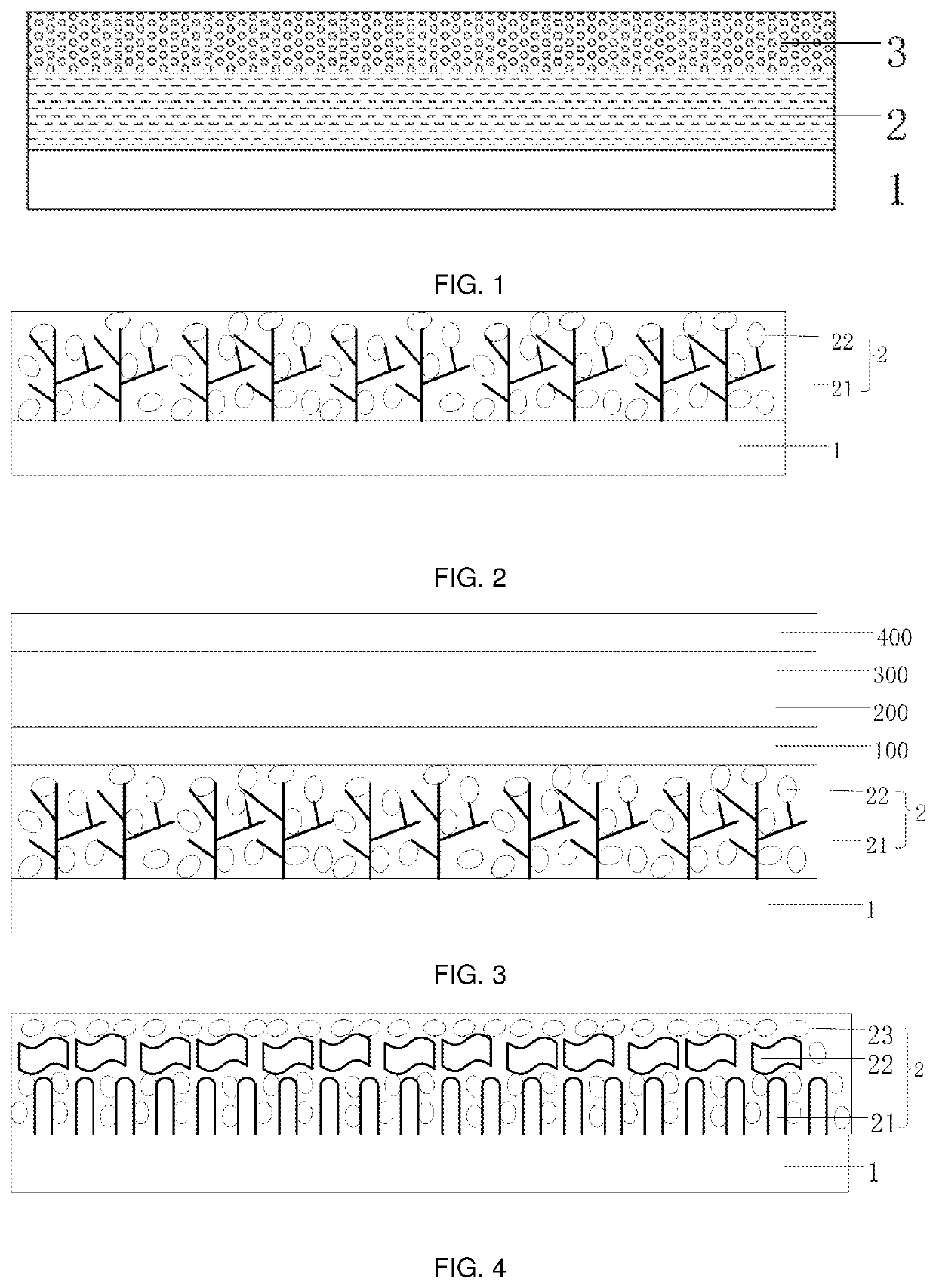
[0030]The embodiment provides a heat dissipation structure for a display panel. Please refer to FIG. 2. FIG. 2 is a structural diagram of a heat dissipation structure according to the present embodiment of the present invention. The heat dissipation structure includes a copper foil layer 1 and a heat conducting layer 2 disposed on the copper foil layer 1. A thickness range of the heat conducting layer is from 50 μm to 150 μm.

[0031]A material of the heat conducting layer 2 includes a heat conducting material 21 having a three-dimensional structure. In this embodiment, the three-dimensional structure of the heat conducting material 21 is a tree-like three-dimensional structure, and a material of the heat conducting material is a porous carbon. In other embodiments, a material of the heat conducting material 21 may also be a carbon fiber meshwork, and is not limited here.

[0032]The tree-like three-dimensional structure heat conducting material 21 establishes more thermal diffusion chann...

embodiment 2

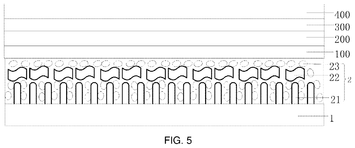
[0042]The embodiment provides a heat dissipation structure for a display panel. Please refer to FIG. 4. FIG. 4 is a structural diagram of a heat dissipation structure according to the present embodiment of the present invention. The heat dissipation structure includes a copper foil layer 1 and a heat conducting layer 2 disposed on the copper foil layer 1. A thickness range of the heat conducting layer is from 50 μm to 150 μm.

[0043]The heat conducting layer 2 includes a one-dimensional heat conducting layer 21 and a two-dimensional heat conducting layer 22, and the one-dimensional heat conducting layer 21 and the two-dimensional heat conducting layer 22 are hybridized to form a longitudinal three-dimensional structure. A material of the one-dimensional heat conducting layer 21 is longitudinal nanotubes, and a material of the two-dimensional heat conducting layer 22 is a longitudinal nanowall.

[0044]In other embodiments, the material of the one-dimensional heat conducting layer 21 may ...


PUM


Abstract

Provided are a heat dissipation structure for a display panel, and a manufacturing method and an application thereof. The heat dissipation structure includes a copper foil layer and a heat conducting layer disposed on the copper foil layer; wherein a material of the heat conducting layer includes a heat conducting material having a three-dimensional structure, and a gap in the three-dimensional structure of the heat conducting material is filled with a buffer.

Description

FIELD OF THE INVENTION[0001]The present invention relates to a display panel field, and more particularly to a heat dissipation structure for a display panel, and a manufacturing method and an application thereof.BACKGROUND OF THE INVENTION[0002]Flexible OLED displays are popular in the display industry due to their low power consumption, high resolution, fast response and bendability. As the thickness thereof is thinner, the market competitiveness of the display can be greater. At present, a flexible material, such as polyimide film (PI) or polyethylene terephthalate (PET) is often used as a substrate. A thin film transistor (TFT), an OLED and a thin film encapsulation (TFE) are sequentially formed on the substrate, and then a polarizer and a glass cover plate are bonded thereon. In order to drive the TFT, it is necessary to bond a chip circuit at the bottom of the flexible substrate to constitute a display panel.[0003]When the display is functioning, the current will heat up throu...

Claims


Application Information

Patent Timeline
Patent Type & Authority Applications(United States)
IPC IPC(8): H05K7/20
CPCH05K7/20481H05K7/20954H05K7/2039H05K7/20963
Inventor WANG, YIJIA
Owner WUHAN CHINA STAR OPTOELECTRONICS SEMICON DISPLAY TECH CO LTD
Learn More