LED illuminator module with high heat-dissipating efficiency and manufacturing method therefor

a technology of illuminator module and manufacturing method, which is applied in the direction of lighting and heating apparatus, semiconductor/solid-state device details, lighting support devices, etc., can solve the problems of short life, unstable light color, low light efficiency, etc., and achieve high heat-dissipating efficiency and manufacturing method, shorten heat-conducting path, and improve heat-dissipation efficiency

Inactive Publication Date: 2013-02-12
CATCHER TECH
View PDF4 Cites 1 Cited by
  • Summary
  • Abstract
  • Description
  • Claims
  • Application Information

AI Technical Summary

Benefits of technology

[0009]The present disclosure provides an LED illuminator module with high heat-dissipating efficiency and manufacturing method, more specifically to solve the heat dissipating problem of a high-power illuminator equipped with a plurality of LED and shorten the heat-conducting path for improving the heat-dissipating efficiency by combining with the flat heat pipe.
[0017]The present disclosure has following advantages.First, the present disclosure did not need circuit board or metallic substrate. Therefore, the heat-conducting path between the LED and the flat heat pipe is shortened to increase heat-dissipating efficiency.
[0018]Next, the present disclosure can optionally provide the partition ring optionally on a periphery of the LED. When the partition ring uses a thermosetting plastic frame, its shape can be easily adjusted with high flexibility.
[0019]Further, the present disclosure can directly use the flat heat pipe to form the concave portion, and the partition ring is not necessary. Then, the LED illuminator module would be thinner. Moreover, the oblique blocking walls could be used for reflecting the light from the LED.

Problems solved by technology

Thus, if heat could not go out properly, many problems will occur such as lowlight efficiency, short lifespan, unstable light color.
However, heat sinks have disadvantages of lower heat-dissipating efficiency and bigger size.
Some prior arts use a heat pipe coordinated with the heat sink to increase the heat-dissipating efficiency but the LED illuminator module manufacture cost would increase as well.
Moreover, all of the aforementioned heat-dissipation ways have the same disadvantage, in which the heat of LED elements has to radiate through a Printed Circuit Board (PCB).
The PCB is a low heat conductive material, so that the heat generated by LED elements can not efficiently and quickly radiate out of the LED illuminator module.
However, the heat generated by the LED elements still need to go through the multi-layers of the MCPCB, thermal grease (or thermal paste) and then arrive the heat pipe.
The retention kit not only increases cost but also has big size.
Besides, assembling the retention kit considerably consumes manpower.

Method used


Image

  • LED illuminator module with high heat-dissipating efficiency and manufacturing method therefor
  • LED illuminator module with high heat-dissipating efficiency and manufacturing method therefor
  • LED illuminator module with high heat-dissipating efficiency and manufacturing method therefor

Examples


first embodiment

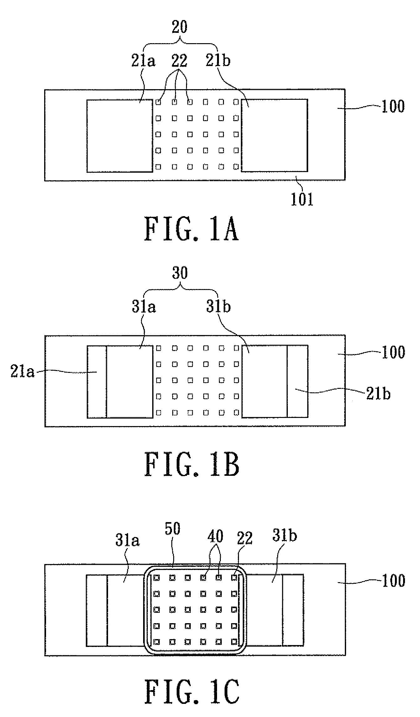
[0030]FIG. 1A to 1E illustrate schematic views of manufacturing processes of an LED illuminator module with high heat-dissipating efficiency of first embodiment according to the present disclosure. In FIG. 1A of the present disclosure, a flat heat pipe (Flat heat pipe, FHP) 100 is provided, and a flat surface 101 is formed on the flat heat pipe 100. The flat heat pipe 100 could be a rectangular board and better with multiple flowing channels, which can increase the volume of working fluid capacity, capillary force, and separate the flows of liquid phase and vapor phase for reducing the friction force between liquid phase and vapor phase.

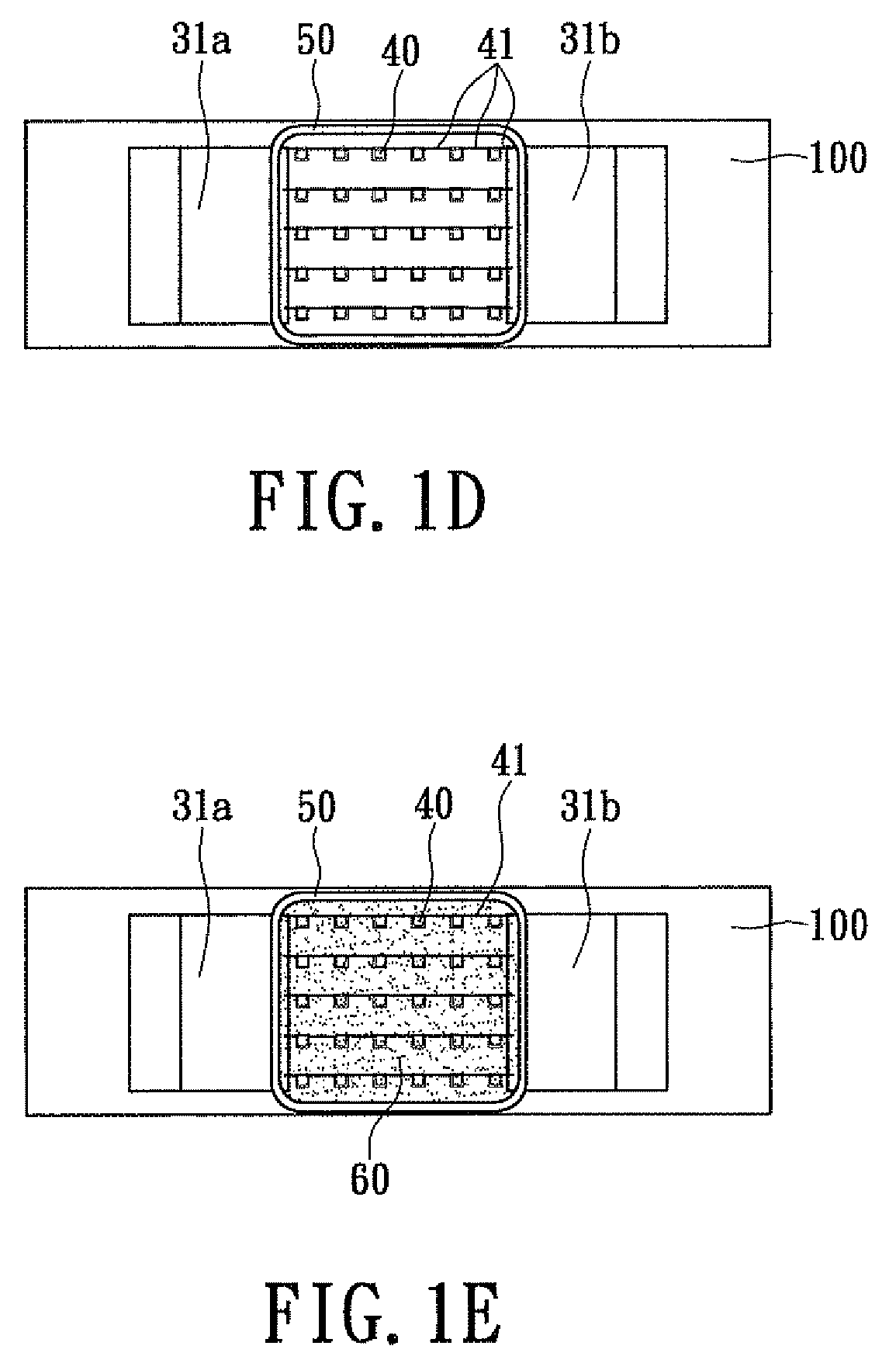
[0031]Moreover, an insulation layer 20 is formed on the flat surface 101 of the flat heat pipe 100. The insulation layer 20 is divided as a pair of insulated electrode portions 21a, 21b, and a plurality of LED-setting portions 22 between the pair of insulated electrode portions 21a, 21b. The function of the insulation layer 20 is used to form a base ...

second embodiment

[0039]Please refer to FIGS. 2A to 2E, which are schematic views for illustrating manufacturing processes for an LED illuminator module with high heat-dissipating efficiency of the second embodiment according to the present disclosure. The difference between FIG. 2A and FIG. 1A is a plurality of insulation strip portions 24 are further provided, which are formed in the step of forming the insulation layer 20. The insulation strip portions 24 are parallel arranged on the flat heat pipe 100 and located between the LED-setting portions 22.

[0040]The difference between FIG. 2A and FIG. 1A is a plurality of conducting strip portions 33 will cover the insulation strip portions 24 in the step of forming the conducting layer 30.

[0041]FIG. 2C is similar with FIG. 1C, in which the LEDs 40 are fixed on the LED-setting portions 22. Besides, the partition ring 50 covers a periphery of the LED 40, to restrict and fix the transparent LED 40 (as shown in FIG. 1, element 60).

[0042]Please refer to FIG....

third embodiment

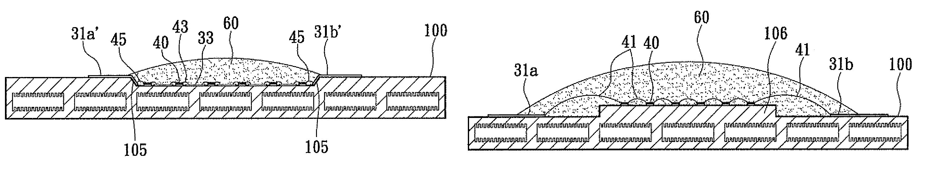
[0048]Please refer to FIG. 7, which is a cross-sectional view of third embodiment of the present disclosure without a partition ring. The difference between this embodiment and FIG. 6 is including the practicing ways of FIGS. 2A to 2E, which includes the conducting strip portions 33 and the insulated strip portions (not shown, be hidden) under the conducting strip portions 33. Further, this embodiment extends the pair of conducting electrode portions 31a′, 31b′ to the oblique blocking walls 105. This embodiment therefore has advantage of omitting the partition ring, using the shorter wires 43, 45 to electrically connect the LED 40 to the conducting strip portions 33 and the pair of conducting electrode portions 31a′, 31b′.


PUM


Abstract

An LED illuminator module with high heat-dissipating efficiency and manufacturing method therefore is provided. The LED illuminator module includes a flat heat pipe (FHP) formed with a flat surface, an insulated layer formed on the plane of the flat heat pipe, a conducting layer having a pair of conducting electrode portions, a plurality of LEDs, and an encapsulation covers the LEDs. The insulation layer has a pair of insulated electrode portions and a plurality of LED-setting portions. The conducting electrode portions partially covered on the insulated electrode portions. The LEDs are disposed on the LED-setting portions and electrically connect to the pair of conducting electrode portions respectively. The encapsulation contains phosphor powder therein. The present invention solves the heat-dissipating problem of high-efficiency light module with the LEDs, and shorten heat-conductive path to enhance heat-dissipating efficiency.

Description

BACKGROUND OF THE INVENTION[0001]1. Field of the Invention[0002]The present disclosure is related to an LED illuminator module with high heat-dissipating efficiency and manufacturing method therefore, more specifically to an illuminator module having multiple LED chips is directly combined with a flat heat pipe and a manufacturing method thereof is also provided.[0003]2. Description of Related Art[0004]Light Emitting Diode (LED) has advantages of small size, long lifespan, low power consumption, luminescence and mercury free so that has become the main research project in illuminating field. The power development of LED is gradually advanced from low-power to high-power and has various application of early indicator light to current LED illuminating products.[0005]Since the high power LED has wide range of applications, the demand of heat dissipation gradually increases. Thus, if heat could not go out properly, many problems will occur such as lowlight efficiency, short lifespan, un...

Claims


Application Information

Patent Timeline
Patent Type & Authority Patents(United States)
IPC IPC(8): F21V33/00
CPCF21K9/00F21K9/90F21V29/006H01L25/0753H05K1/0272F21Y2101/02F21Y2105/001H01L23/24H01L33/648H05K2201/09745H05K2201/10106H01L2224/45147H01L2224/45124H01L2224/45144H01L24/45H01L2924/00014H01L2224/48091H01L2224/48137H01L2924/01047H01L2924/00H01L2924/12041F21Y2105/10F21Y2115/10H01L2924/181F21V29/51H01L2924/00012
Inventor CHEN, YAN-HUA
Owner CATCHER TECH
Why Eureka
Try Eureka