Fast-acting high-current controlled fuse

A high current, fuse technology, applied in the direction of circuits, electrical components, emergency protection devices, etc.

Pending Publication Date: 2018-12-11
XIAMEN SET ELECTRONICS
View PDF4 Cites 1 Cited by
  • Summary
  • Abstract
  • Description
  • Claims
  • Application Information

AI Technical Summary

Problems solved by technology

[0006] When there is a high-voltage DC relay failure or other failures that need to be cut off within 5 seconds, the current market lacks such a fuse mechanism that uses fusible alloys to quickly cut off high-current protection devices to ensure the safe operation of electric vehicles.

Method used


Image

  • Fast-acting high-current controlled fuse
  • Fast-acting high-current controlled fuse
  • Fast-acting high-current controlled fuse

Examples


Embodiment 1

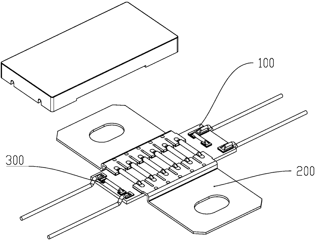
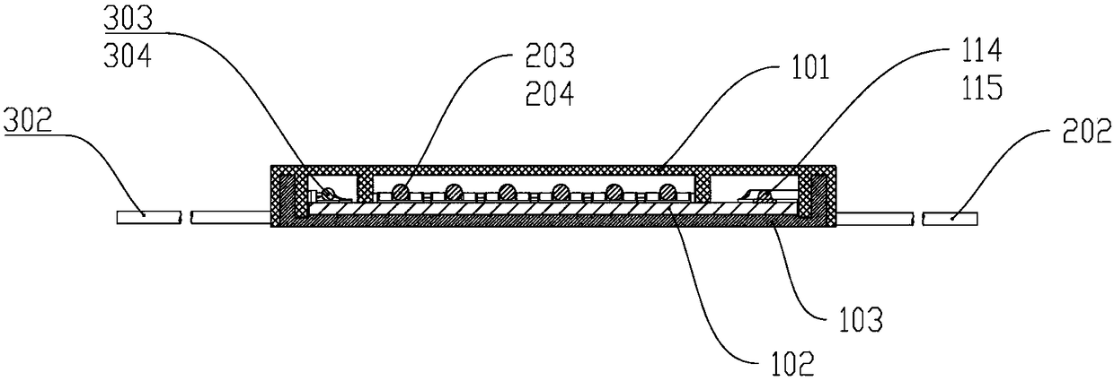
[0061]The fast-acting high-current controlled fuse of the present invention includes a heating device 100 and a current-through device 200 . The flow-through device 200 includes two sheet-shaped left electrode pins 201 and right electrode pins 202 separated from each other, and one or more first fuses connected between the two pieces of electrode pins. The left electrode pin 201 and the right electrode pin 202 are provided with grooves, parallel to the heating device 100 , and both include a stepped portion, and the lower edge of the stepped portion is flush with the lower edge of the heating device 100 .

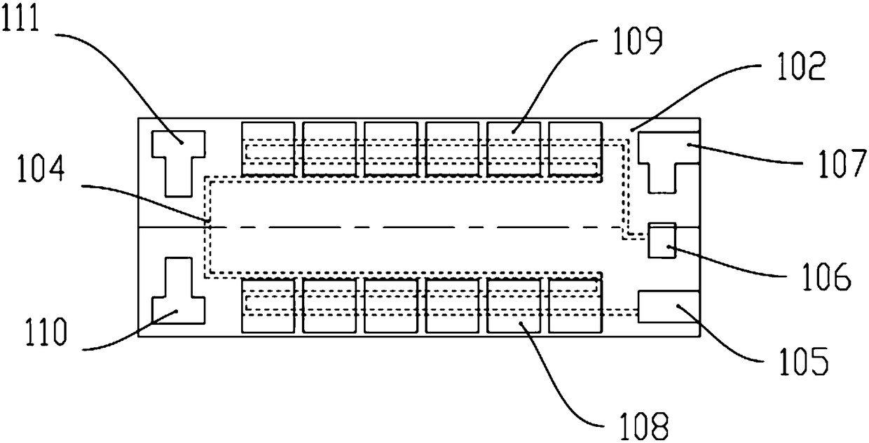
[0062] Such as image 3 As shown, the two ends of the heating device 100 close to the surface of the flow-through device 200 are respectively provided with a left flow-through pad 108 and a right flow-through pad 109, and the left electrode pin 201 includes a left groove 2011, which is welded on the left flow-through pad 109. On the pad 108, an independent welding point is...

Embodiment 2

[0069] In the present invention, the second fusing device may not be provided. At this time, the third operating temperature of the third fusing device only needs to be higher than the first operating temperature, so that after the first fusing device is fused, the third fusing device continues to be heated until the temperature reaches the third temperature. Action temperature, the third fusing device is fused, thereby sending out a remote signaling signal, informing the system that the cut-off function has been executed.

Embodiment 3

[0071] The flow-through device 200 can also be connected with a high breaking device in parallel to improve the breaking capacity. The high-breaking device can be a fusible alloy that is greatly affected by temperature, or a current fuse that is greatly affected by current. When it is a fusible alloy, the fusible alloy whose action temperature is higher than the first action temperature, when it is a current fuse, its internal resistance is greater than the internal resistance of the first fusing device.


PUM


Abstract

The invention provides a fast-acting high-current controlled fuse, which comprises a heating device and a flow device. The flow device comprises two mutually-separated electrode pins, and one or morefirst fuse devices connected between the two electrode pins. The first fuse device has a first acting temperature. The first fuse device is arranged close to the heating device and is insulated from the heating device. Since the fuse device in the flow device is close to the heating device, heat conduction path is shortened and power loss caused by heat diffusion is reduced; when the system detects fault and starts heating, a cut-off instruction can be carried out quickly; due to a self overtemperature protection function, thermal runaway of a heating sheet is prevented; and a remote signalingfunction is added to provide a remote signaling signal to notify the system that the cut-off instruction is carried out.

Description

technical field [0001] The invention relates to a fuse, in particular to a fast-acting large-current controlled fuse. Background technique [0002] With the development of the electric vehicle industry, the endurance of power batteries has become a bottleneck in the development of electric vehicles. In order to solve this problem, the capacity of the power battery is getting bigger and bigger, and at the same time, the platform voltage is increased to reduce reactive power loss. At present, in the electronic control system of electric vehicles, the positive and negative high-voltage power supply lines of the power battery are connected in series with high-voltage DC relays controlled by the Battery Management System (BMS). The on-board battery and the like are connected to the high-voltage power supply line of the power battery. In addition to the above-mentioned high-voltage DC relay, there are manual maintenance switches installed on the power battery and current fuses c...

Claims


Application Information

Patent Timeline
Patent Type & Authority Applications(China)
IPC IPC(8): H01H85/00H01H85/055H01H85/143
CPCH01H85/0047H01H85/055H01H85/143
Inventor 洪尧祥郭友德
Owner XIAMEN SET ELECTRONICS
Why Eureka
Try Eureka