Wireless charging receiving terminal

A wireless charging and receiving end technology, applied in coils, circuits, electrical components, etc., can solve the problems of large interface thermal resistance and affect the heat dissipation of modules, and achieve the effect of improving heat dissipation performance, reducing thickness, and shortening the heat conduction path.

Active Publication Date: 2018-11-06
VIVO MOBILE COMM CO LTD
View PDF8 Cites 1 Cited by
  • Summary
  • Abstract
  • Description
  • Claims
  • Application Information

AI Technical Summary

Problems solved by technology

[0005] Embodiments of the present invention provide a method for preparing a wireless charging receiving end and its terminal equipment, so as to solve the problem of the large interface thermal resist

Method used


Image

  • Wireless charging receiving terminal
  • Wireless charging receiving terminal
  • Wireless charging receiving terminal

Examples


Embodiment Construction

[0023] The following will clearly and completely describe the technical solutions in the embodiments of the present invention with reference to the accompanying drawings in the embodiments of the present invention. Obviously, the described embodiments are some of the embodiments of the present invention, but not all of them. Based on the embodiments of the present invention, all other embodiments obtained by persons of ordinary skill in the art without creative efforts fall within the protection scope of the present invention.

[0024] The technical solutions provided by various embodiments of the present invention will be described in detail below in conjunction with the accompanying drawings.

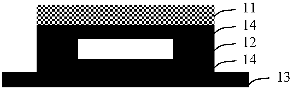
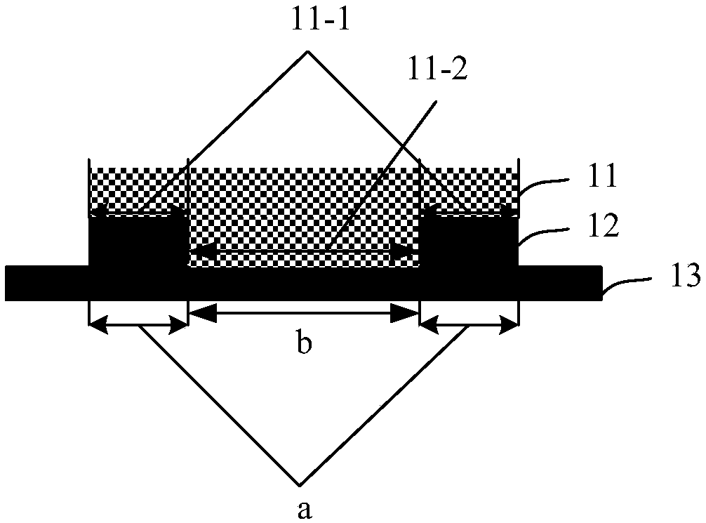
[0025] In order to solve the above-mentioned problems existing in the prior art, the embodiment of the present invention provides a wireless charging receiver, compared with the prior art, such as figure 2 As shown, it is a schematic structural diagram of a wireless charging receivin...


PUM

PropertyMeasurementUnit
Adhesionaaaaaaaaaa
Thermal conductivityaaaaaaaaaa
Permeabilityaaaaaaaaaa

Abstract

The invention discloses a wireless charging receiving terminal, which is used for solving the problem that the thermal resistance of the interface between the double-sided glue, the magnetic conductive module and the substrate in wireless charging receiving terminal in the prior art is large, thereby affecting the heat dissipation of the whole module. The wireless charging receiving end comprisesa magnetic permeability module, a coil and a substrate, wherein, one end of the coil is arranged on the substrate; the magnetic conductive module has a magnetic conductive substrate, and a protrusionprotruded from the middle of the magnetic conductive substrate, the magnetic conductive substrate has a coil curing region surrounding the protrusion; the coil curing region is bonded and fixed in theother end, opposite to the substrate, of the coil; the protrusion extends into the middle of the coil and is adhered and fixed on the substrate.

Description

technical field [0001] The present invention relates to the technical field of wireless charging, in particular to a wireless charging receiving end. Background technique [0002] With the rapid development of smart mobile terminals, the wireless charging technology applied to smart mobile terminals has gradually become the technical commanding heights that many high-tech companies compete for. Among them, the electromagnetic induction wireless charging technology has become the best choice for smart mobile terminals due to its lower development and production costs, higher charging efficiency and better miniaturization design. [0003] In order to improve the charging efficiency of electromagnetic induction wireless charging, a magnetically permeable material with high magnetic permeability is usually used as a magnetically permeable module. At present, the receiving end of the wireless charging of the smart mobile terminal usually adopts figure 1 The structure shown incl...

Claims


Application Information

Patent Timeline
IPC IPC(8): H01F5/00
CPCH01F5/003
Inventor 易小军
Owner VIVO MOBILE COMM CO LTD
Why Eureka
Try Eureka