Reclining seat assembly

a seat and assembly technology, applied in the field of reclining seats, can solve the problems of generating aesthetically-less-desirable gaps and pivoting, and achieve the effects of increasing the knee room of the rear seat passenger, maximizing aesthetics, and increasing the foot spa

Active Publication Date: 2016-06-02
FCA US
View PDF3 Cites 1 Cited by
  • Summary
  • Abstract
  • Description
  • Claims
  • Application Information

AI Technical Summary

Benefits of technology

[0006]For example, in an exemplary embodiment, the seat frame includes a pair of laterally-spaced side members whose rear portions define a first pair of transversely-aligned bores which cooperate with complementary projections or pins on the backrest frame to define the backrest pivot axis, about which the backrest frame is pivotally supported on the seat frame. A second set of transversely-aligned bores formed within downward extensions of the backrest frame in turn define the rear seat pan pivot axis, about which to pivotally support the rear portion of the seat pan using a pair of complementary, outwardly-extending projections on the seat pan. It will be appreciated that the use of such integrally-formed projections on a contoured seat pan can advantageously obviate the need for a rigid cross-member that otherwise typically extends across the rear of the seat frame, beneath the rear of the seat cushion, thereby improving available foot room for rear seat passengers.
[0008]In accordance with another aspect of the invention, the backrest pivot axis as defined by the seat frame is preferably located relatively forward of the rearward-most backrest cushion surface when the backrest frame is in an upright position, to thereby position the backrest pivot axis relatively closer to the nominal hip joint of a seated passenger. Still further, because the rear portion of the seat pan is pivotally coupled to the backrest frame along the rear seat pan pivot axis, the gap formed between the seat cushion and the backrest cushion is preferably optimized for aesthetics and seated passenger comfort through optimization of the offset between the backrest and rear seat pan pivot axes. A formed structural seat pan, as supported by the backrest frame for pivotal movement about the rear seat pan pivot axis, advantageously provides additional foot room for passengers seated behind the seat assembly, while a formed structural backrest frame advantageously provides increased rear seat passenger knee room, and legroom relative to known reclining seats.

Problems solved by technology

The rearward placement of known backrest pivots may also generate an aesthetically-less-desirable gap between the seat cushion and the backrest cushion as the inclination of the backrest is changed.

Method used


Image

  • Reclining seat assembly
  • Reclining seat assembly
  • Reclining seat assembly

Examples


Embodiment Construction

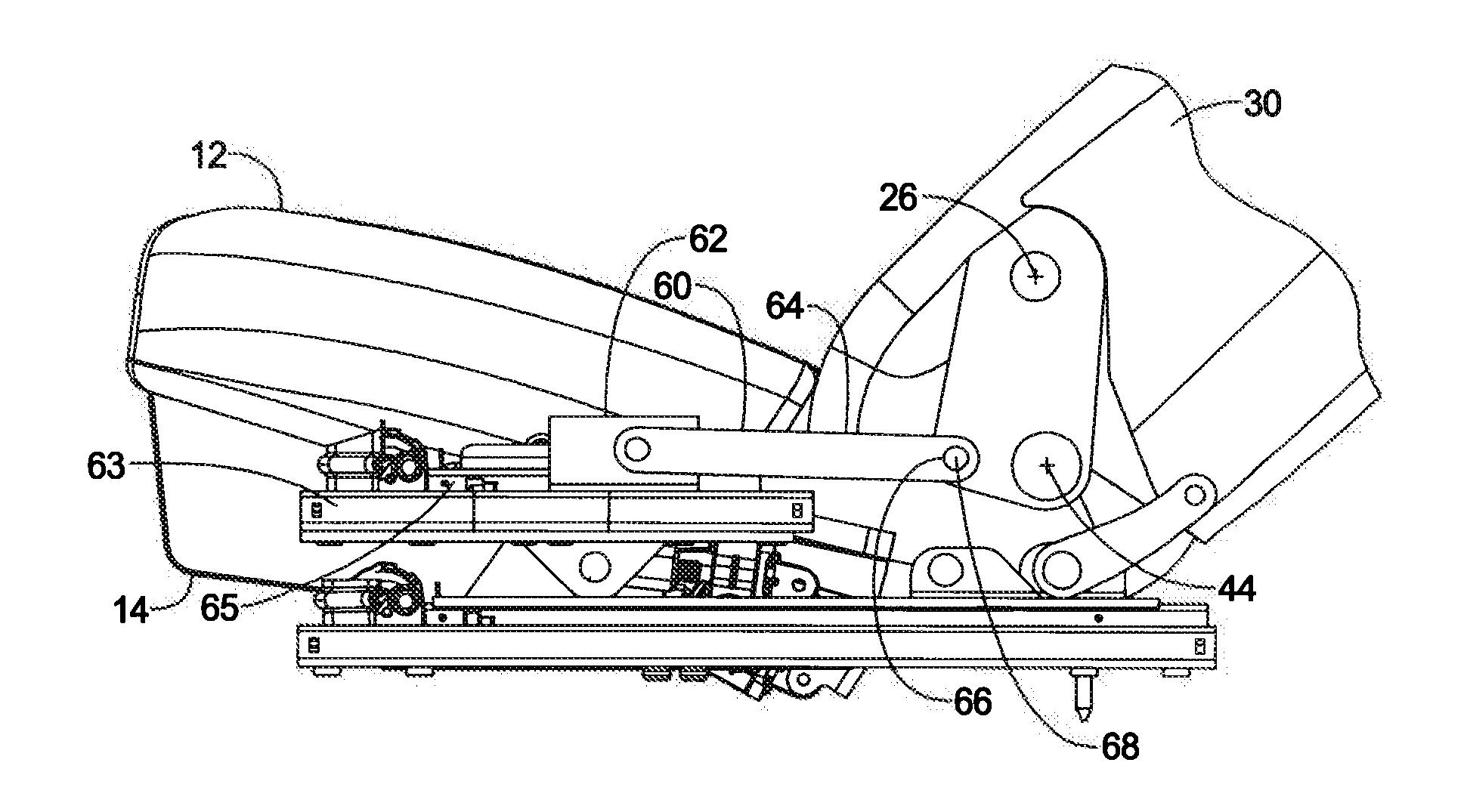
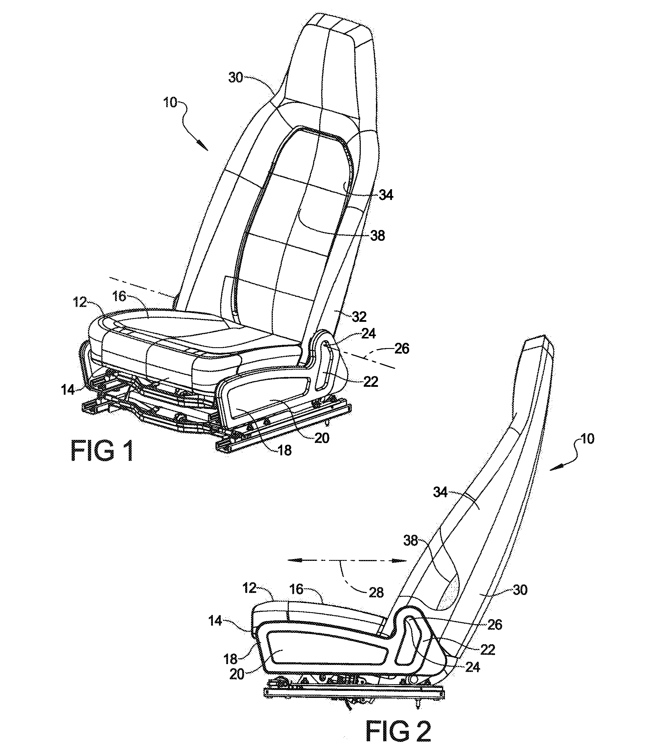
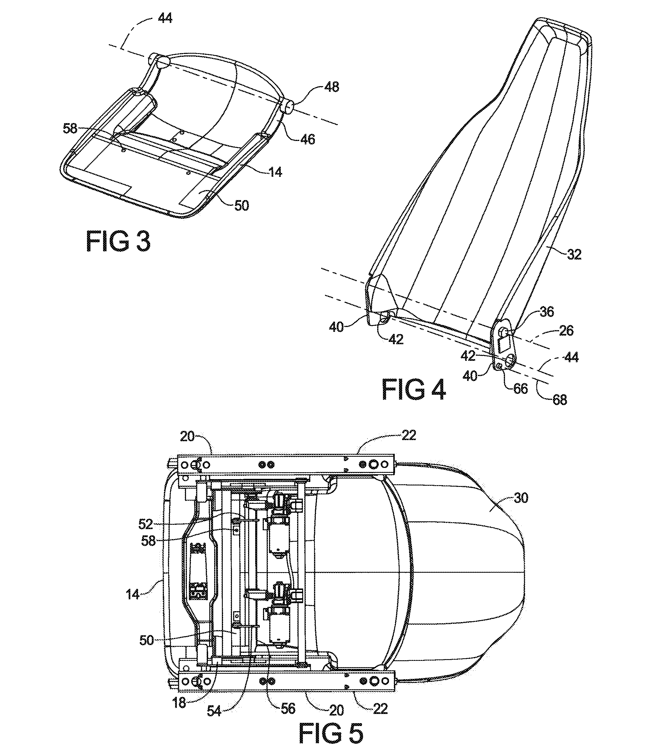
[0018]Referring to FIGS. 1-5, a first exemplary reclining seat assembly 10 for a vehicle includes a bottom seat (hereinafter “seat 12”) including a seat pan 14 and seat cushion 16 supported atop a seat frame 18. The seat frame 18 includes side members 20 whose raised rear portions 22 include a first pair of transversely-aligned bores 24 with which to define a backrest pivot axis 26 that, in the case of a forward-facing vehicle seat assembly, is generally perpendicular to the nominal longitudinal axis 28 of the vehicle.

[0019]A seat back or backrest 30 including a backrest frame 32 and backrest cushion 34 is supported on the seat frame 18 for pivoting movement about the backrest pivot axis 26 by a pair of complementary projections 36 on the backrest frame 32 that are pivotally received within the seat frame's side member bores 24. As best seen in FIGS. 1 and 2, the backrest pivot axis 26 as defined by the side members 20 is located relatively forward of the backrest cushion's central ...


PUM


Abstract

A reclining seat assembly includes a seat frame, and a backrest frame supported by the seat frame for pivoting movement about a backrest pivot axis. A seat pan has a forward portion supported by the seat frame for relative longitudinal movement, for example, using a slider. The seat pan has a rearward portion that is pivotally supported along a rear seat pan axis by a lower extension of the backrest frame, such that the backrest frame reclines relative to the seat frame upon forward longitudinal movement of the rear seat pan pivot axis relative to the seat frame. A backrest recline angle adjuster on the seat frame, such as a pair of linear actuators respectively coupling the seat frame to each side of the backrest frame along an actuator pivot axis that is itself offset from the backrest pivot axis, maintains a selected position of the rear seat pan support axis relative to the seat frame to thereby achieve a desired backrest inclination.

Description

CROSS-REFERENCE TO RELATED APPLICATIONS[0001]This application is a divisional of U.S. patent application Ser. No. 13 / 347,815 filed on Jan. 11, 2012. The entire disclosure of the above application is incorporated herein by reference.FIELD OF THE INVENTION[0002]The invention relates to reclining seats, particularly those employed in a relatively forward one of a plurality of rows of seats in a passenger vehicle, such as the vehicle's front row seats.BACKGROUND OF THE INVENTION[0003]Known reclining seat designs for vehicles typically employ seat and backrest cushion supports that each include a suspension matt stretched between spaced frame members to respectively support the seat and backrest cushions. The relative outboard location of these spaced frame members within the seat and backrest means that these seat and backrest frame members occupy space, for example, along the lateral edges of the backrest that might otherwise be used to accommodate rear seat passengers, particularly th...

Claims


Application Information

Patent Timeline
Patent Type & Authority Applications(United States)
IPC IPC(8): B60N2/12B60N2/68
CPCB60N2/12B60N2/686B60N2/68B60N2/0284B60N2/0705B60N2/2209B60N2/233
Inventor FINCK, JAMES W.
Owner FCA US
Why Eureka
Try Eureka