Iris recognition lens system

Active Publication Date: 2016-06-30
SEKONIX
View PDF0 Cites 52 Cited by
  • Summary
  • Abstract
  • Description
  • Claims
  • Application Information

AI Technical Summary

Benefits of technology

[0023]According to the present invention as set forth above, a single lens has a plurality of reflecting areas and a plurality of transmitting areas in order to reduce the length of the lens and increase a focal length, thereby reducing the length of t

Problems solved by technology

When a lens having a short focal length is used, it is very uncomfortable since the eye must be placed close to the lens to take the image of the iris.
However, when an eye is photographed at an eye-to-lens distance of 250 mm using this lens, an iris image has a very small size rang

Method used


Image

  • Iris recognition lens system
  • Iris recognition lens system
  • Iris recognition lens system

Examples


first embodiment

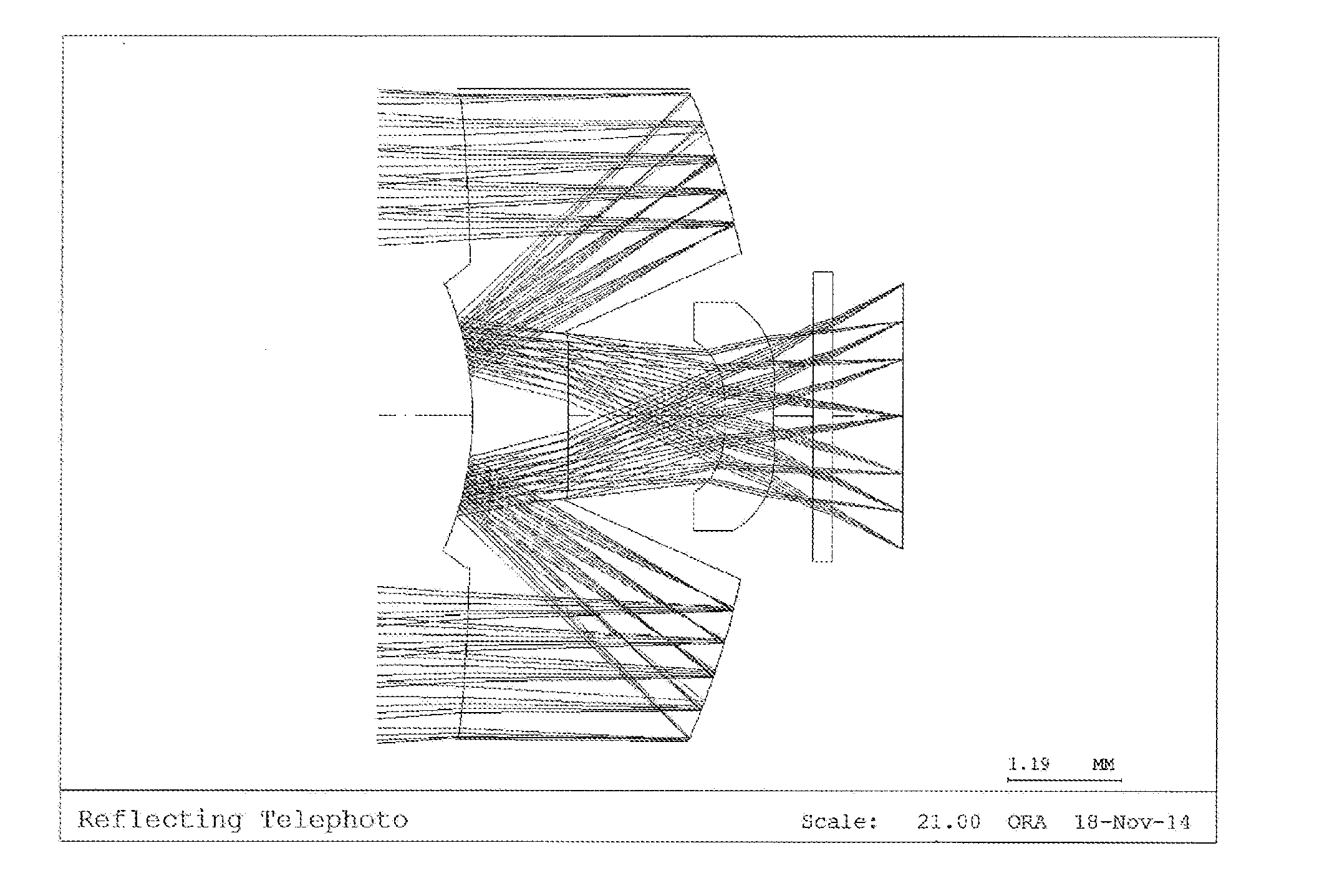
[0058]FIG. 2 a diagram illustrating a first exemplary embodiment according to the iris recognition lens system of the present invention.

[0059]As illustrated in FIG. 2, a first lens is disposed on an optical axis at a predetermined distance from an object, and a second lens compensating for imaging is additionally disposed at a position facing a transmitting area of a rear part of the first lens.

[0060]Table 1 below presents data about the lens constituting an optical system according to the first embodiment of the present invention.

TABLE 1SurfaceTHINo.RDY1)(thickness)Nd2)Vd3)R / T4)OBJINFINITY2501INFINITYTTL / f AIR0.50823692−80.2549631.53155.8T5)STO−8.14847−2.994241.53155.8R6)4−3.0905111.53155.8R6)5−8240.770381.650175Air6−2.834730.51.53155.8T5)75.489480.414821Air8INFINITY0.2BSC7_HOYAT5)9INFINITY0.739662IMGINFINITY−0.003Notes)RDY1): RDY (radius of curvature),Nd2): Nd (refractive index),Vd3): Vd (Abbe number),R / T4): Reflection / Transmission,T5): Transmission,R6): Reflection(OBJ: Surface of...

second embodiment

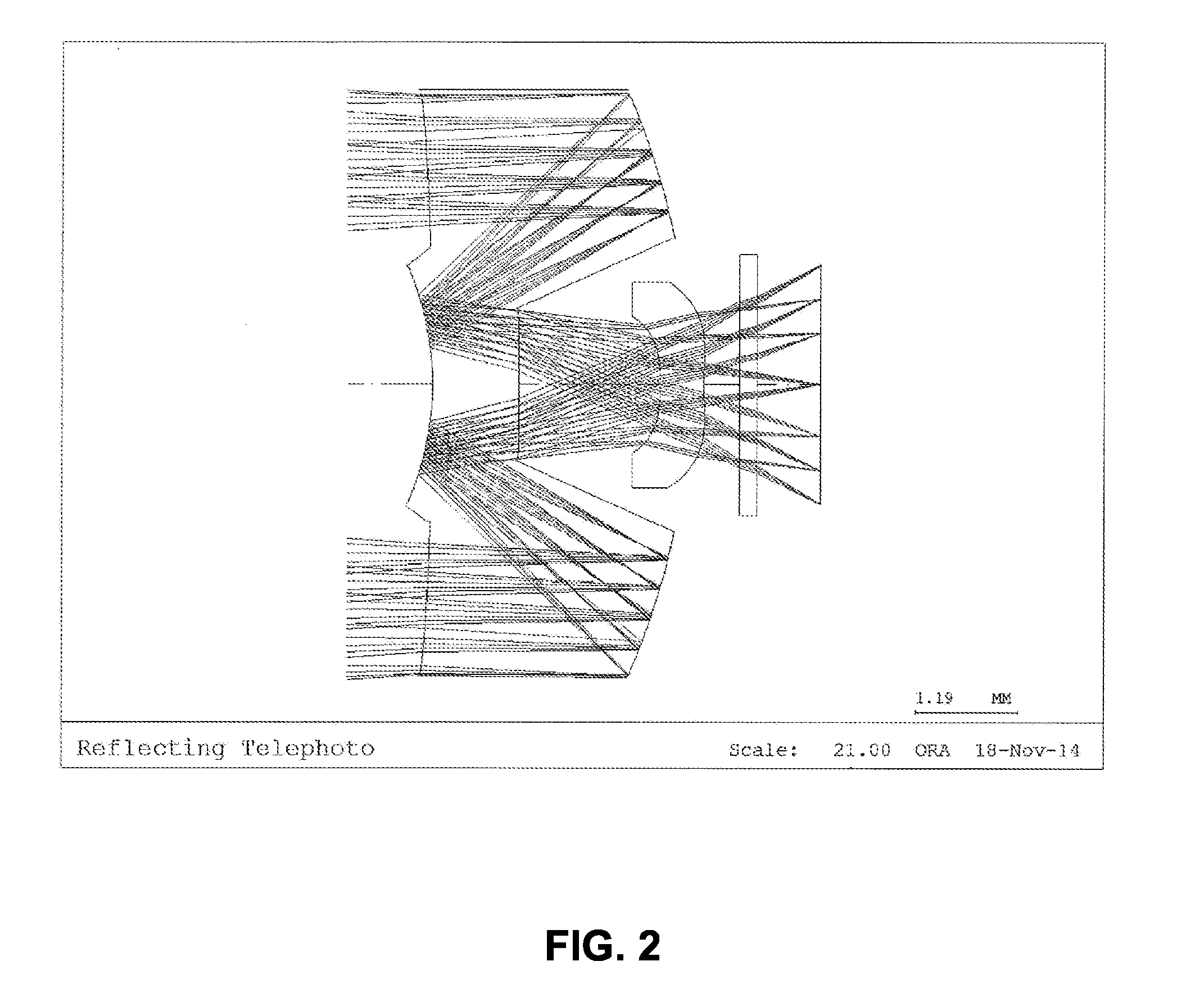
[0070]FIG. 4 is a schematic view illustrating a second exemplary embodiment according to the iris recognition lens system of the present invention.

[0071]As illustrated in FIG. 4, a first lens is disposed on an optical axis at a predetermined distance from an object, and a second lens compensating for imaging is additionally disposed at a position facing a transmitting area of a rear part of the first lens.

[0072]Table 4 below presents data about the lens constituting an optical system according to the second embodiment of the present invention.

TABLE 4SurfaceTHINo.RDY1)(thickness)Nd2)Vd3)R / T4)OBJINFINITY2501INFINITY0.482369AIR2−82.9176431.53155.8T5)STO−8.03947−2.994241.53155.8R6)4−2.780391.51.53155.8R6)5−25.607291.788945Air6−0.859860.41.53155.8T5)7−2.052570.90144Air8INFINITY0.2BSC7_HOYAT5)9INFINITY0.719449IMGINFINITY−0.003Notes)RDY1): RDY (radius of curvature),Nd2): Nd (refractive index),Vd3): Vd (Abbe number),R / T4): Reflection / Transmission,T5): Transmission,R6): Reflection(OBJ: Surfa...

third embodiment

[0082]FIG. 6 is a schematic view illustrating a third exemplary embodiment according to the iris recognition lens system of the present invention.

[0083]As illustrated in FIG. 6, a first lens is disposed on an optical axis at a predetermined distance from an object, and a second lens compensating for imaging is additionally disposed at a position facing a transmitting area of a rear part of the first lens.

[0084]Table 7 below presents data about the lens constituting an optical system according to the third embodiment of the present invention.

TABLE 7SurfaceTHINo.RDY1)(thickness)Nd2)Vd3)R / T4)OBJINFINITY2501INFINITY0.482369AIR2−87.1647731.53155.8T5)STO−7.89313−2.994241.53155.8R6)4−2.666691.51.53155.8R6)5−708.625041.28214air6−0.932390.51.53155.8T5)7−2.40820.198294air8INFINITY0.2BSC7_HOYAT5)9INFINITY1.171931IMGINFINITY−0.003Notes)RDY1): RDY (radius of curvature),Nd2): Nd (refractive index),Vd3): Vd (Abbe number),R / T4): Reflection / Transmission,T5): Transmission,R6): Reflection(OBJ: Surface...


PUM

PropertyMeasurementUnit
Fractionaaaaaaaaaa
Lengthaaaaaaaaaa
Diameteraaaaaaaaaa

Abstract

An iris recognition lens system including a first lens and a second lens disposed on an optical axis and sequentially from an object to take an image of an iris and a pupil. A front part of the first lens includes a reflecting area in a central portion and a transmitting area in a circumferential portion. A rear part of the first lens includes a concave transmitting area in a central portion and a reflecting area in a circumferential portion. The second lens is disposed at a rear of the transmitting area in the central portion of the rear part of the first lens. A plurality of reflecting areas and a plurality of transmitting areas are provided in a single lens in order to reduce the length of the lens and increase a focal length, thereby reducing the length of the entire iris recognition lens system.

Description

CROSS REFERENCE TO RELATED APPLICATION(S)[0001]This application claims the benefit of Korean Patent Application No. 10-2014-0193657, filed on Dec. 30, 2014, which is hereby incorporated by reference in its entirety into this application.BACKGROUND OF THE INVENTION[0002]1. Field of the Invention[0003]The present invention generally relates to an iris recognition lens system. More particularly, the present invention relates to an iris recognition lens system in which a single lens has a plurality of reflecting areas and a plurality of transmitting areas in order to reduce the length of the lens and increase a focal length, thereby reducing the length of the entire iris recognition lens system.[0004]2. Description of the Related Art[0005]Iris recognition is a technology for taking an image of an iris through a lens, encoding the image according to a pattern, storing the encoded image, and comparing and determining whether an input image is identical with the stored image. The accuracy ...

Claims


Application Information

Patent Timeline
IPC IPC(8): G02B17/08G02B13/24G02B13/18G02B1/04G02B13/00
CPCG02B17/0808G02B1/041G02B17/0856G02B13/18G02B13/24G02B13/0095G02B3/00G02B3/0037G02B9/60G06V40/19G02B13/06G02B3/02G02B17/023
Inventor CHOI, SOON CHULJEGAL, CHANG S.KIM, YANG S.LEE, YOUNG J.
Owner SEKONIX
Why Eureka
Try Eureka