Drive Mechanism for a Needle Insertion Arrangement

Active Publication Date: 2016-07-28
SANOFI AVENTIS DEUTSCHLAND GMBH
View PDF3 Cites 4 Cited by
  • Summary
  • Abstract
  • Description
  • Claims
  • Application Information

AI Technical Summary

Benefits of technology

[0005]It is an object of the present invention to provide an

Problems solved by technology

Administering an injection is a process which presents a number of risks and challenges for users and healthcare professionals, both mental and physical.
During manual insertion of a

Method used


Image

  • Drive Mechanism for a Needle Insertion Arrangement
  • Drive Mechanism for a Needle Insertion Arrangement
  • Drive Mechanism for a Needle Insertion Arrangement

Examples


Embodiment Construction

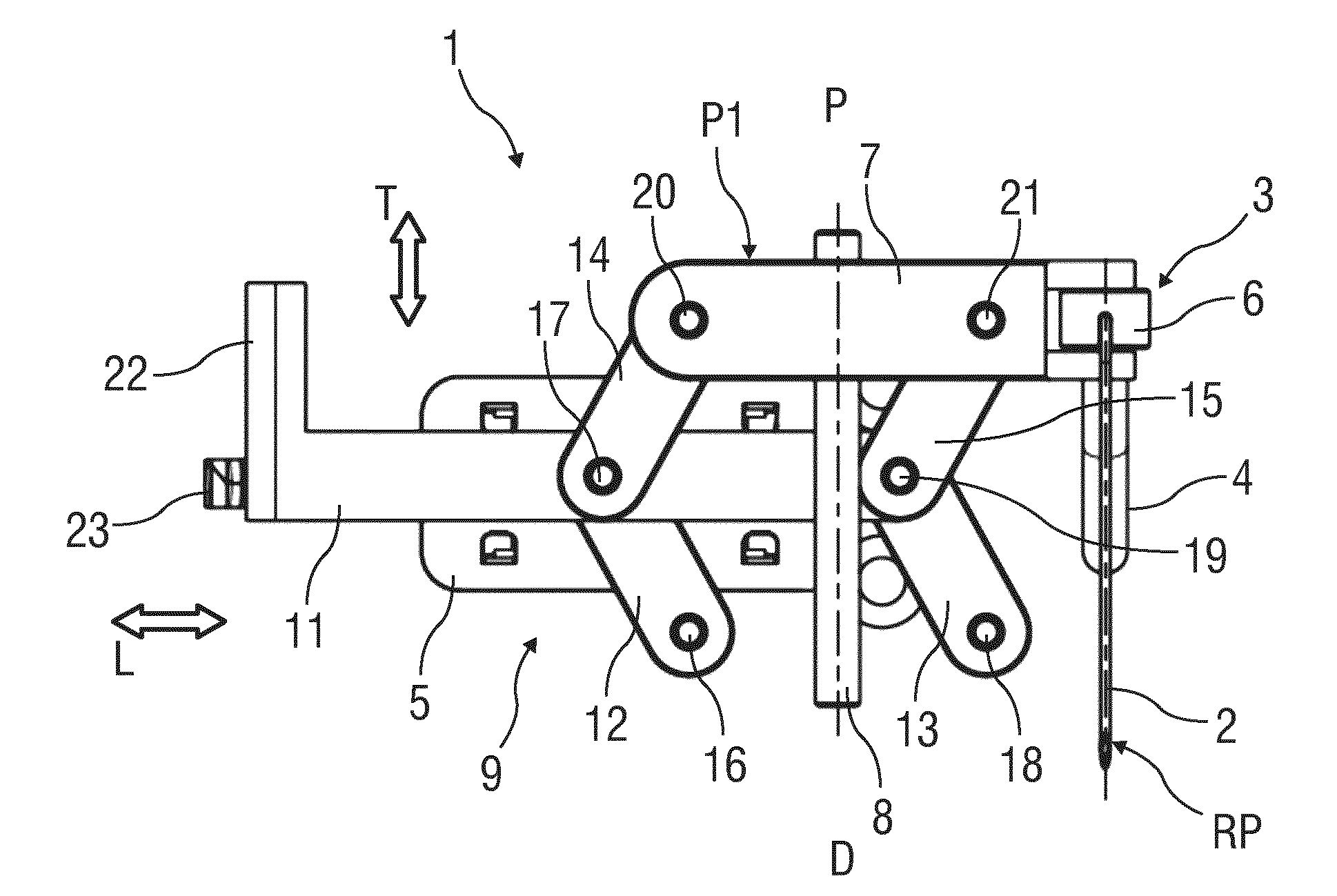
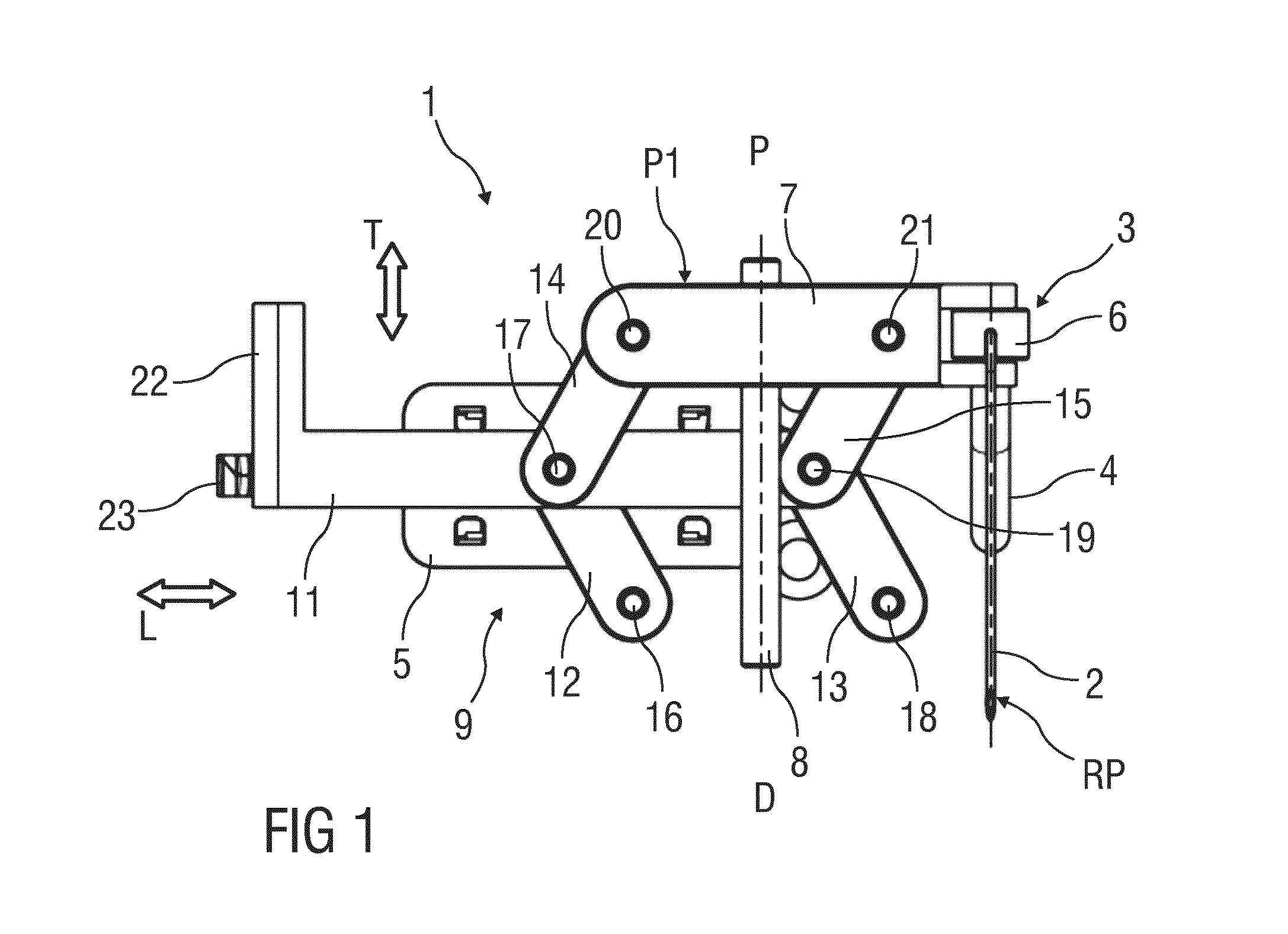
[0028]FIG. 1 is a schematic view of an exemplary embodiment of an insertion arrangement 1 for automatically or semi-automatically inserting an injection needle 2 into an injection site. The injection may be performed manually or by a motor. The arrangement 1 may be applied in medicament pumps, e.g. insulin pumps which may be permanently worn on the body.

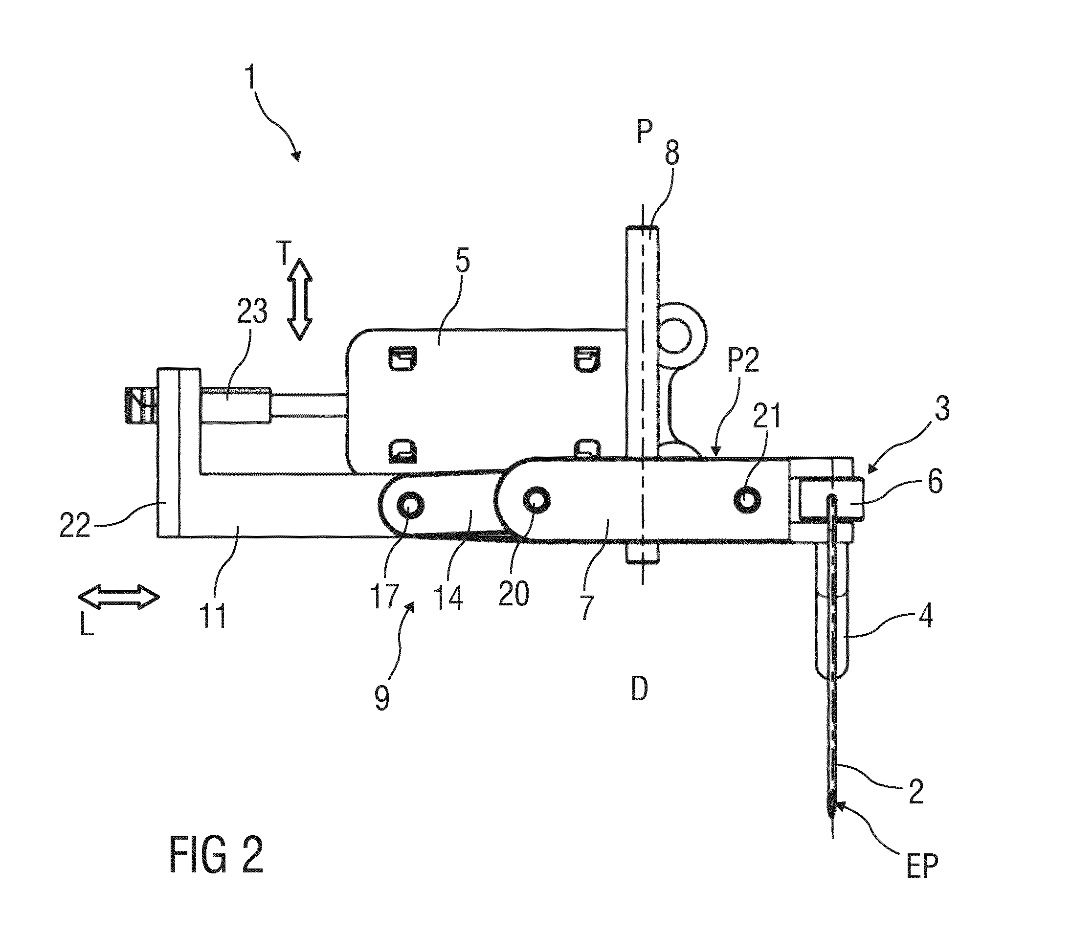
[0029]The injection needle 2 is part of a disposable unit 3, further comprising a tube 4 for establishing a fluid communication of the needle 2 with a drug container (not illustrated) and comprising a needle base 6, to which the injection needle 2 may be fixed for mechanically connecting the needle 2 to a drive mechanism 9 of an injection unit (not illustrated). The needle base 6 is inserted in a forked needle retainer 7 which is arranged to be moved between a retracted position RP and an extended position EP in a linear guide 8. This linear movement corresponds to insertion of the needle 2 into the injection site, e.g. subcutaneous ...


PUM


Abstract

The invention relates to a drive mechanism (9) for a needle insertion arrangement (1), the drive mechanism (9) comprising an actuator (5) coupled to a parallel linkage (10) adapted to convert a linear movement of the actuator (5) in a longitudinal direction (L) to a linear movement of a cross beam (7) in transverse direction (T) substantially at right angles with respect to the longitudinal direction (L).

Description

TECHNICAL FIELD[0001]The invention relates to a drive mechanism for a needle insertion arrangement.BACKGROUND OF THE INVENTION[0002]Administering an injection is a process which presents a number of risks and challenges for users and healthcare professionals, both mental and physical. During manual insertion of an injection needle into an injection site, e.g. the skin of a patient, it may be difficult to avoid tilting and bending of the needle and the insertion may be slow thus causing pain.[0003]EP 2 460 553 A1 discloses a device having a mounting formed of piston and connector movably mounted inside a body. A needle is secured to the mounting and a drive unit formed of propulsion unit, and spring drives the mounting toward an outer ring. The mounting is arranged so as to reach a position after activating the drive unit in which a distal surface of the mounting relative to a proximal end is more distant than contact area, where the device is arranged so as to enable a gradual passi...

Claims


Application Information

Patent Timeline
IPC IPC(8): A61M5/158
CPCA61M2005/1585A61M5/158
Inventor SCHABBACH, MICHAELWERNER, MEINOLFZECKAI, OLAFNZIKE, PHILIPPE
Owner SANOFI AVENTIS DEUTSCHLAND GMBH
Why Eureka
Try Eureka