

Remote Catheter Positioning System with Hoop Drive Assembly
- Summary
- Abstract
- Description
- Claims
- Application Information
AI Technical Summary
Benefits of technology
Problems solved by technology
Method used
Image

Examples
Embodiment Construction
[0021]Various embodiments will be described in detail with reference to the accompanying drawings. Wherever possible, the same reference numbers will be used throughout the drawings to refer to the same or like parts. References made to particular examples and implementations are for illustrative purposes and are not intended to limit the scope of the invention or the claims.
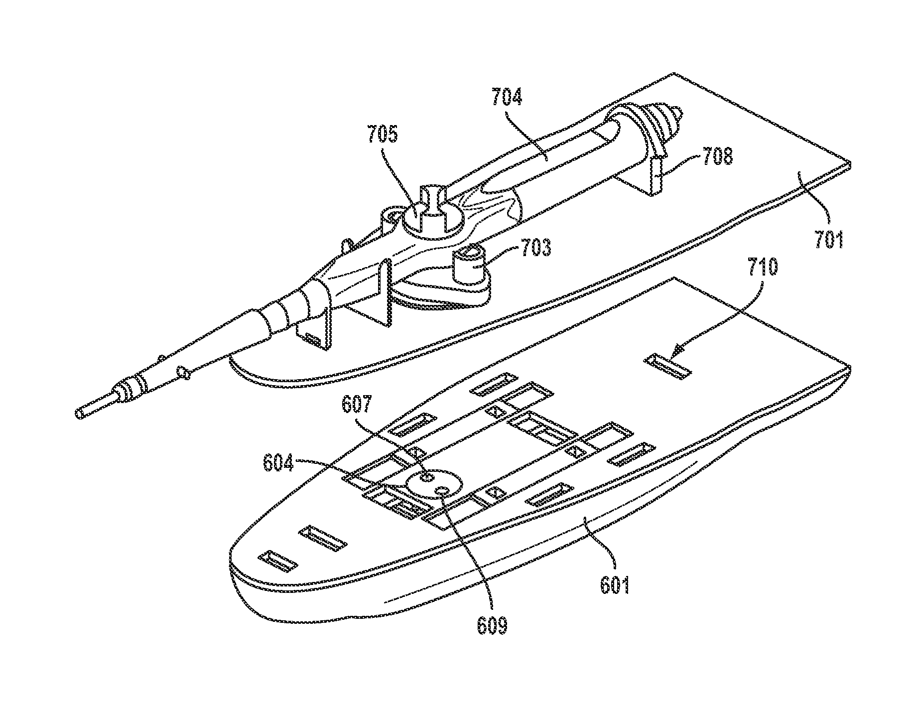
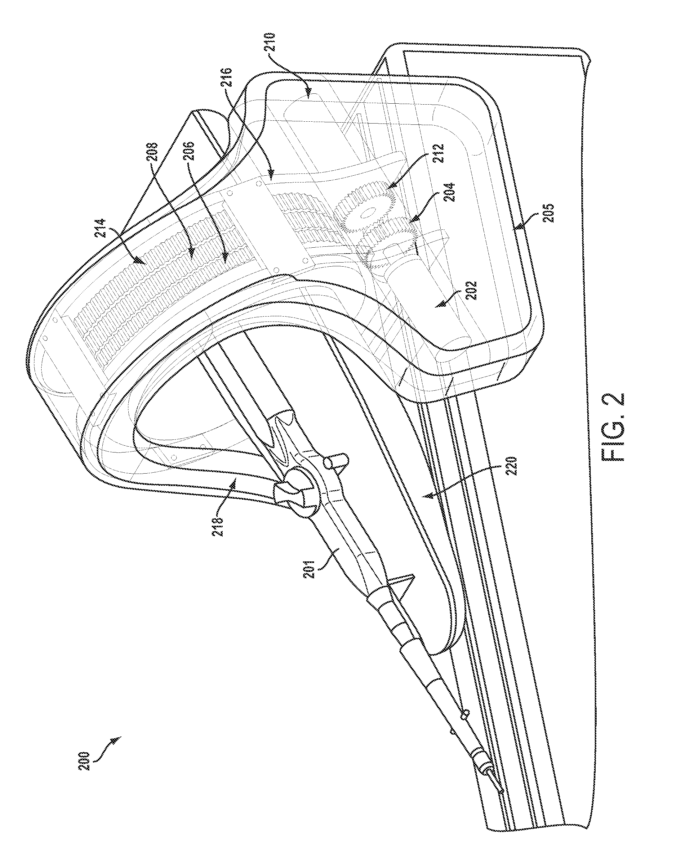
[0022]Systems, methods, and devices of the various embodiments provide hoop drive assemblies for use with catheter positioning systems. The hoop drive assemblies according to the various embodiments may include one or more toothed rings and one or more motors coupled to the one or more toothed rings. The one or more motors coupled to the one or more toothed rings may be any type of motors, such as servomotors, hydraulic motors, etc. An example servo motor may include a sensor providing position feedback to a servomotor controller. An example hydraulic motor may include a hydraulic motor suitable for use in magne...
PUM
 Abstract
Description
Claims
Application Information