

Marker
a marker and marker technology, applied in the field of writing utensils, can solve the problems of wasting ink, wasting markers, and wasting markers, and achieving the effect of reducing the number of marks
- Summary
- Abstract
- Description
- Claims
- Application Information
AI Technical Summary
Benefits of technology
Problems solved by technology
Method used
Image

Examples
embodiment 100
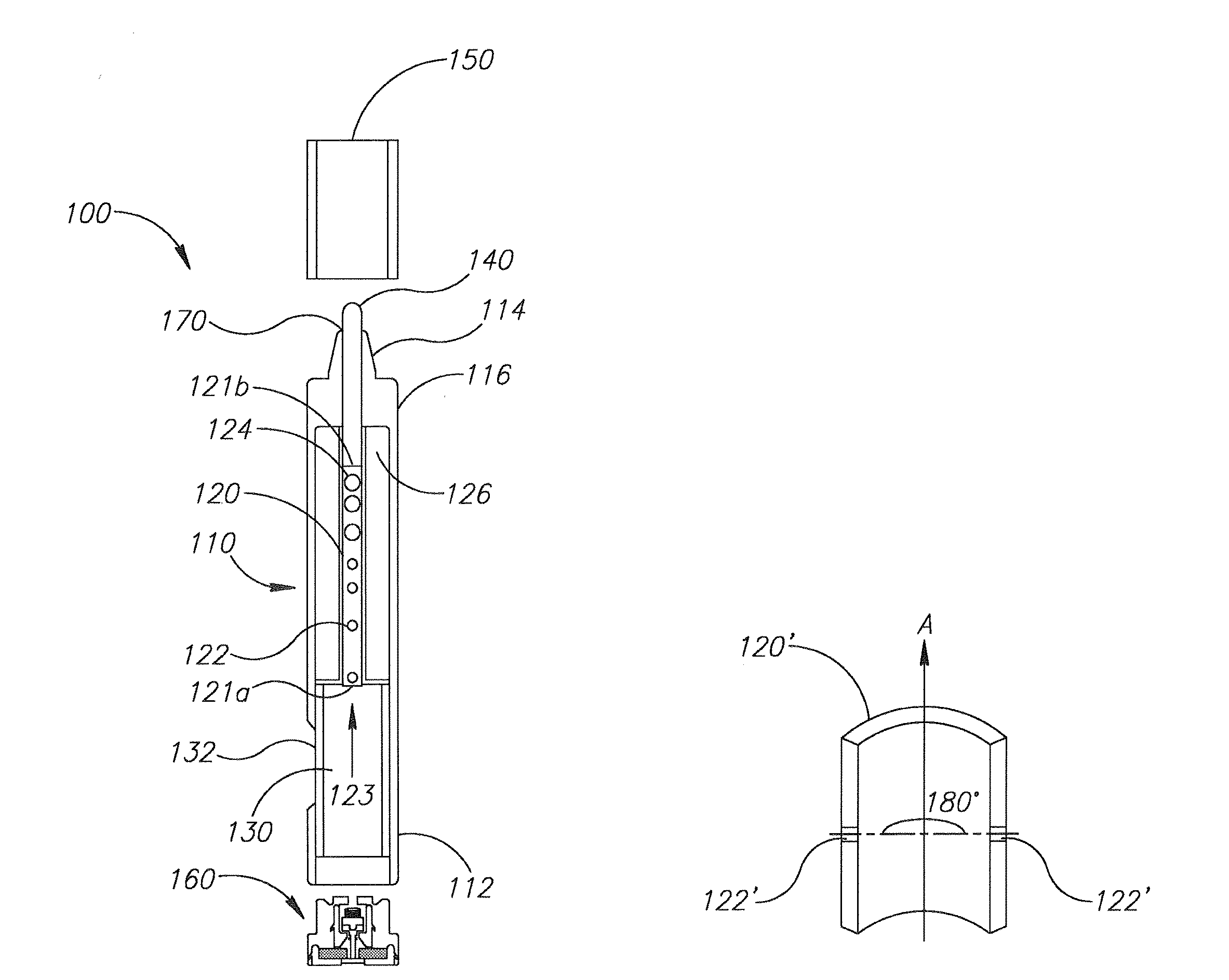
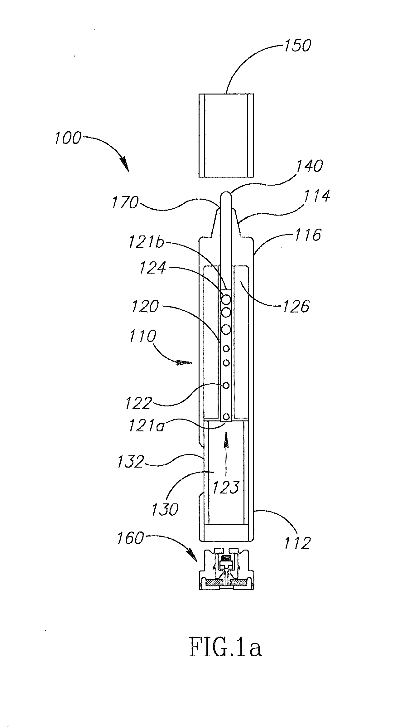
[0064]Reference is now made to FIG. 1 a showing the marker embodiment 100 having a body 110 and a pen core (writing head) 140. The body 110 has a bottom part 112 and a top part 114.
[0065]The marker 100 has several special features that include a flow-pipe 120 with holes 122 and 124, and a reservoir 130.
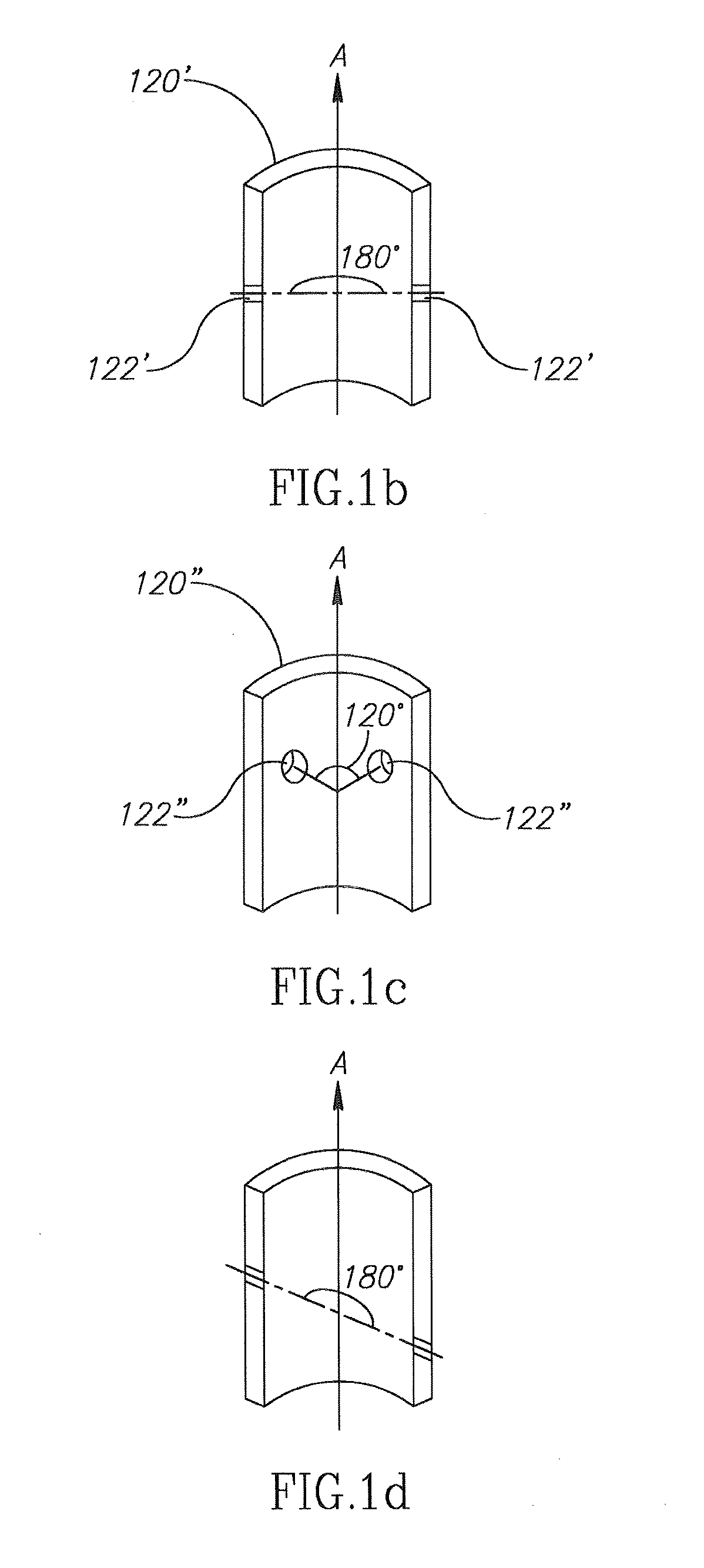
[0066]The flow-pipe 120 is embedded in an absorber 126, which comprises ink-absorbent material. The flow-pipe 120 is hollow therein and is preferably open at the bottom end 121a and closed at the top end 121b. There are at least two holes in the flow-pipe 120, preferably evenly arranged around the flow-pipe 120, so that whichever position the marker is held during use, ink can flow out of the flow-pipe into the absorber 126. FIG. 1b, 1c show cross sections of flow pipe 120′, 120″, respectively, halved along their length, with examples of such arrangements, with holes 122′, 122″ respectively: in pipe 120″ the angle between the holes 122″ is about 120° relative to the centre of the pipe...
embodiment 200
[0081]Therefore, as shown in FIGS. 2a-2e, another marker embodiment 200 is provided, which includes venting-tubes 280 in the reservoir 230. The role of the tubes is to transfer air trapped in the absorber 226 to the reservoir 230 when using the marker 200, such as writing with it on a board or filling the core 240 / absorber 226 with ink, and to increase the speed of transfer of ink from the reservoir 230 to the absorber 226. The tubes 280 allow balancing the pressure between inside the absorber 226 and inside the reservoir 230, allowing the liquid and air to flow through smoothly. Note that as shown in FIG. 2e, the tubes 280 are not connected directly to the absorber 226; there is preferably a small gap 281 between the absorber 226 and the venting tubes 280.
[0082]The description below further clarifies the structure and how the marker 200 may work.
[0083]Referring in particular to FIG. 2a, the marker 200 has a particularly long core 240, extending from outside the marker 200 to a core...
first embodiment
[0087]It will occur that some embodiments may comprise both the reservoir with the holders for the venting-tubes, and the flow pipe, wherein the core is shorter like in the
[0088]FIG. 3a shows yet another marker embodiment 300 that indeed has a shorter core 340, and comprises both the venting tubes 380 and the flow pipe 320, which again has larger holes 324 and smaller holes 322. As in the first embodiment 100, the marker 300 has a reservoir 330 and a groove 370 between the body 316 and the core 340 allowing passage of air (air may be forced out of the marker 300 while refilling and air may enter the marker 300 during writing). The marker 300 also comprises a refill mechanism 360. However the refill mechanism 360 does not include a spring but rather the resilient means 368 is a crown, shown in an end cap 367 in FIG. 3b, and alone in FIGS. 3c-3e: FIG. 3c is a perspective view, 3d a top view, 3e is a side view. The crown 368 is essentially a flat seal with multiple fingers 369 thereon....
PUM
 Abstract
Description
Claims
Application Information