System and method for controlling at least one variable during layup of a composite part using automated fiber placement

Active Publication Date: 2017-02-16
GENERAL ELECTRIC CO
View PDF3 Cites 5 Cited by
  • Summary
  • Abstract
  • Description
  • Claims
  • Application Information

AI Technical Summary

Benefits of technology

[0006]Briefly, one aspect of the present disclosure resides in an automated in-line manufacturing system for controlling at least one variable during layup of a composite part using automated fiber placement. The automated in-line manufacturing system including an automated layup system and a controller. The automated layup system is configured to receive a feed-through of one or more fiber tows as an input material and provide layup of the one or more fiber tows to form a laminate of one or more laid up plies. The controller is configured to respond to measurement data obtained in one or more samplings and adjust a layup program of the one or more fiber tows to compensate for a variation from one or more of a reference weight of the input material and a reference weight of the laminate.
[0007]Another aspect of the disclosure resides in an automated in-line manufacturing system for controlling at least one of a thickness and a weight of a composite part manufactured with the automated in-line manufacturing system. The automated in-line manufacturing system including an automated layup system and a controller. The automated layup system is configured to receive a feed-through of one or more fiber tows as an input material and provide layup of the one or more fiber tows to form a laminate of one or more l

Problems solved by technology

Yet, in large rotating components such as composite fan blades found in gas turbine engines, in which tip speeds may reach speeds close to the speed of sound, any variation in external shape and

Method used


Image

  • System and method for controlling at least one variable during layup of a composite part using automated fiber placement
  • System and method for controlling at least one variable during layup of a composite part using automated fiber placement
  • System and method for controlling at least one variable during layup of a composite part using automated fiber placement

Examples


Example

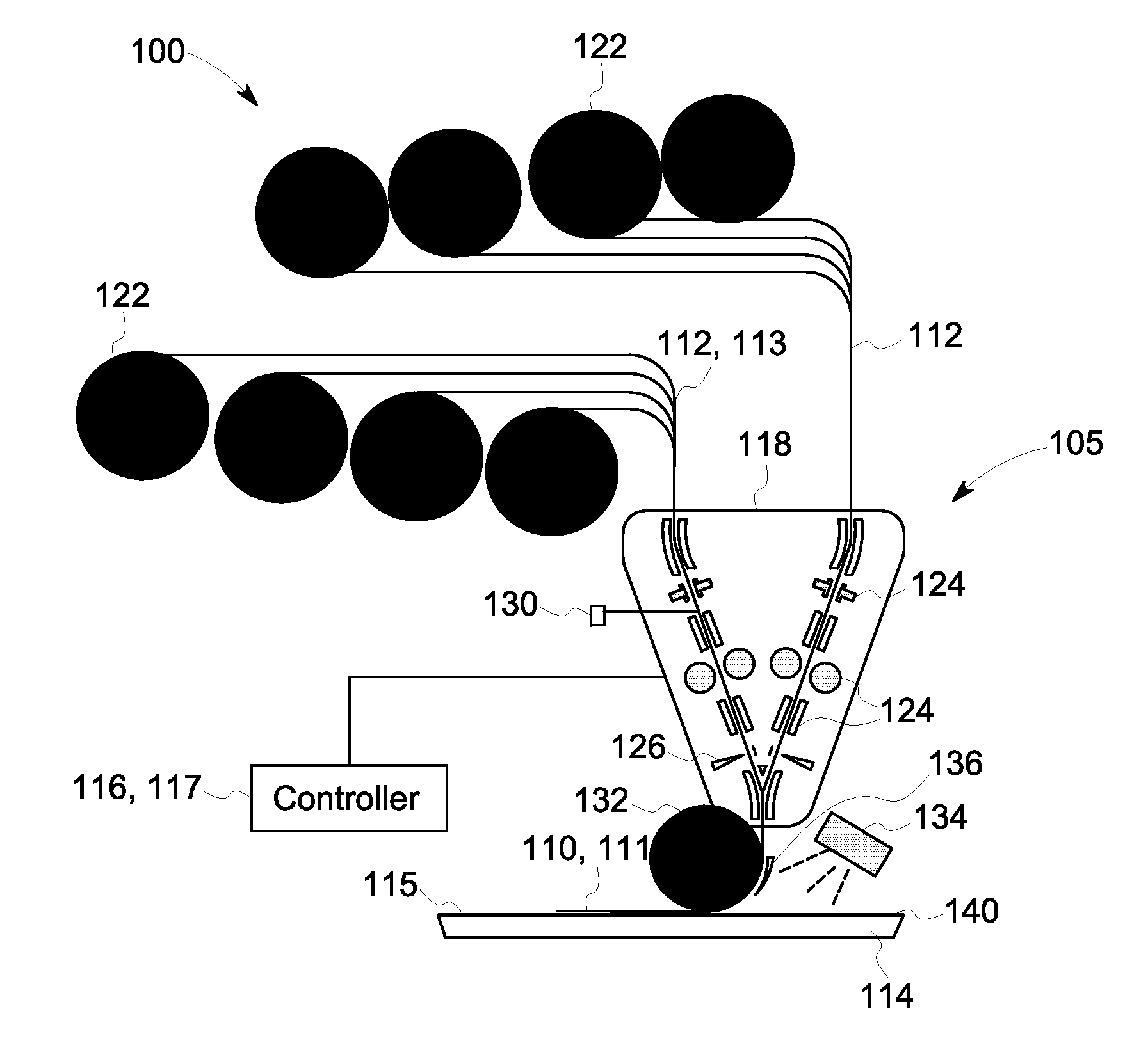
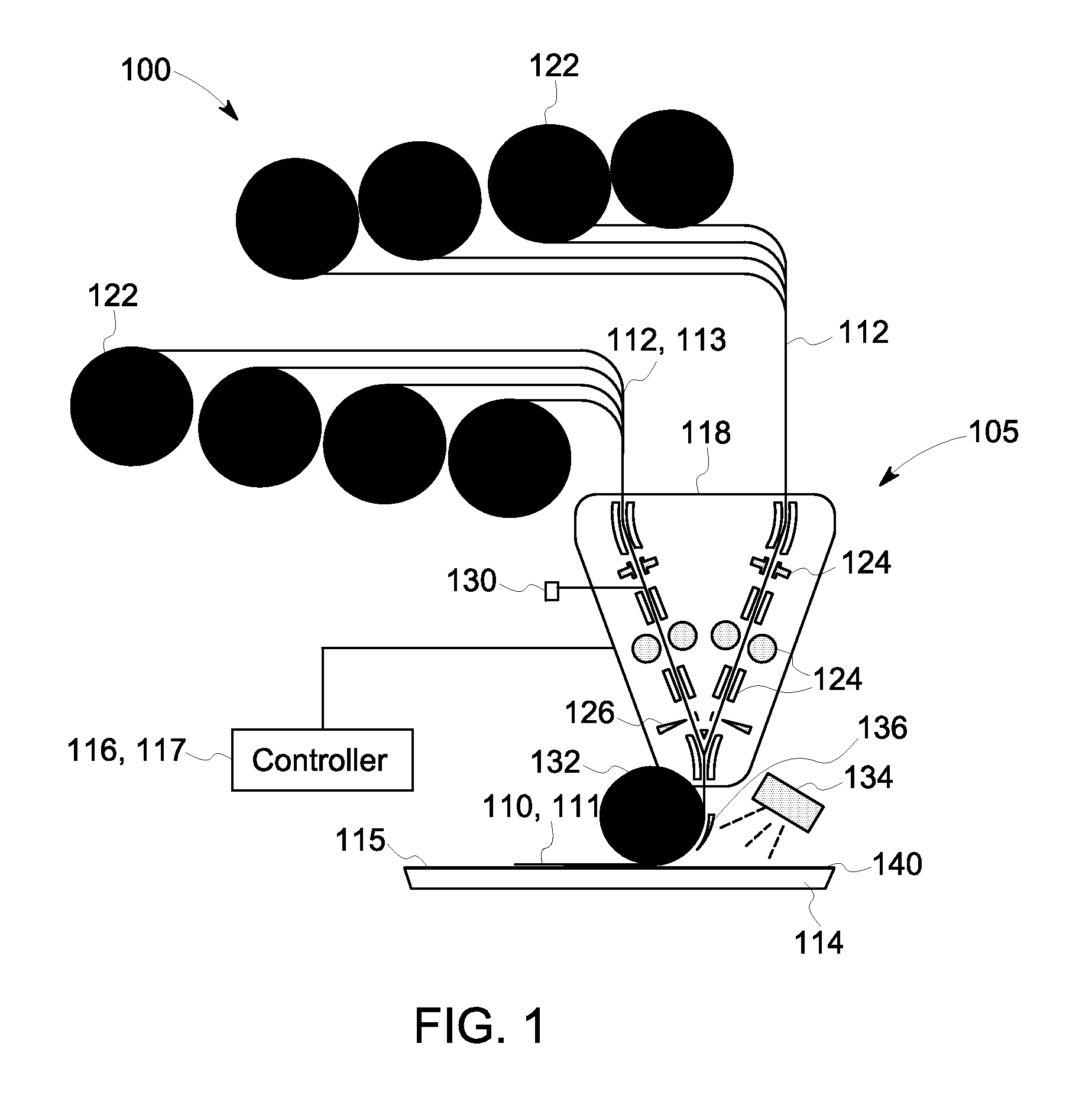
[0016]A composite automated in-line manufacturing system 100, including an automated in-line layup system 105 and a controller 116 is disclosed for the layup of one or more fiber tows 112, as an input, or parent, material 113, to form a composite part 140, as described generally with reference to FIG. 1. The automated in-line manufacturing system 100 can be used for controlling the thickness and weight of a composite part 140, non-limiting examples of which include low weight, high strength aircraft and automotive parts. More specifically, FIG. 1 is a diagrammatic illustration of one embodiment of the automated in-line manufacturing system 100 in accordance with aspects of the present disclosure for layup of the one or more fiber tows 112, such as on to a substrate 114, to form a laminate 110 of one or more laid up plies 111. As used herein, the term “substrate” may include a film, a mold, a tool, or the like used for fabrication of a composite part. The substrate 114 may be manuall...


PUM

PropertyMeasurementUnit
Weightaaaaaaaaaa
Flow rateaaaaaaaaaa
Lengthaaaaaaaaaa

Abstract

An automated in-line feed-through system and method, integrates the ability to control one or more variables during part fabrication with the layup of one or more fiber tows to form a composite part. The system includes an automated layup system configured to receive a feed-through of one or more fiber tows as an input material. The automated in-line feed-through system further includes a controller configured to respond to measurement data obtained by one or more samplings of the input material and/or a plurality of laid up plies that form a laminate. The controller in response to the obtained measurement data provides adjustment of the feed-through of the one or more fiber tows to compensate for a variation in one or more of the weights from a reference weight.

Description

BACKGROUND[0001]The disclosure relates generally to automated fiber placement systems and methods and, more particularly, to a system and method for controlling one or more variables during fabrication of composite parts using automated fiber placement.[0002]With the introduction of automated layup process, such as Automated Fiber Placement (AFP) and Automated Tape Laying (ATL), an automated and more cost effective method of producing composite parts may be utilized. Yet, in large rotating components such as composite fan blades found in gas turbine engines, in which tip speeds may reach speeds close to the speed of sound, any variation in external shape and between neighboring blades as a result of manufacturing variances using these automated layup processes, may have a large impact on noise and aerodynamic losses leading to higher fuel consumption. As an example, for fan blade manufacturing, in order to make a conforming fan blade, it must have the correct thickness to meet aerod...

Claims


Application Information

Patent Timeline
IPC IPC(8): B29C70/30B29C65/00
CPCB29C66/01B29C70/30B29C70/382B29C70/384B29C70/386B29C70/388B29C70/54B29C70/342G01N21/8422G01N2021/8472
Inventor MADSEN, CHRISTOPHER JAMESUPADHYAY, RAM KUMARVAN NIEUWENHOVE, STEFAAN GUIDOKLUGE, THOMASMESSMER, MATHIAS ERNSTPETERSEN, MARTIN
Owner GENERAL ELECTRIC CO
Why Eureka
Try Eureka