Current sensor
- Summary
- Abstract
- Description
- Claims
- Application Information
AI Technical Summary
Benefits of technology
Problems solved by technology
Method used
Image
Examples
first embodiment
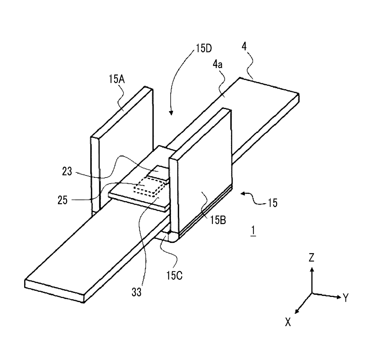
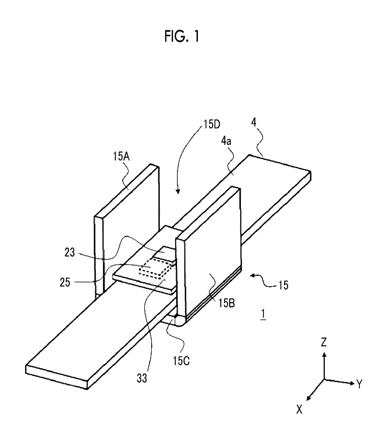
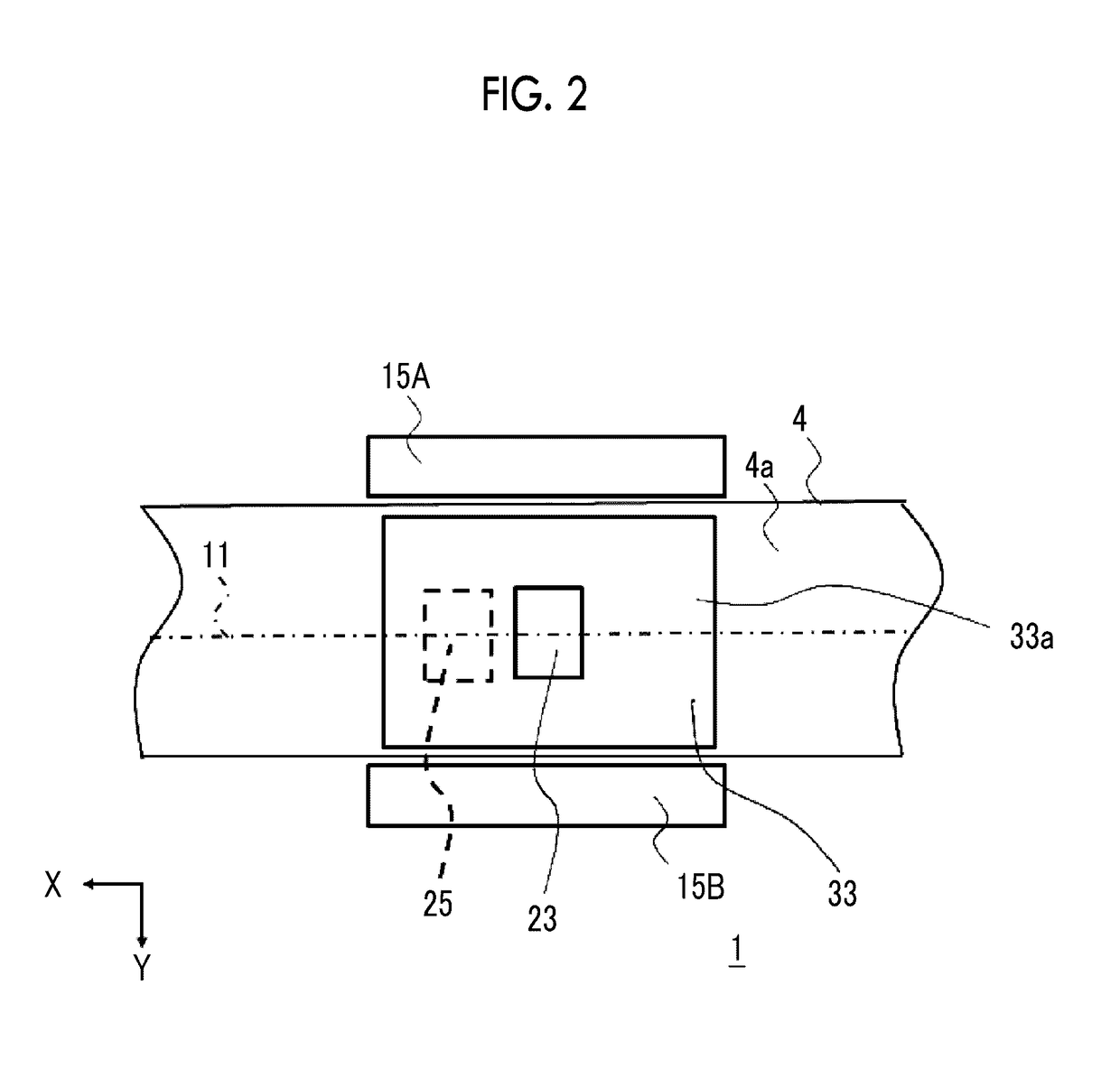
[0041]FIG. 1 is a perspective view showing the appearance of a current sensor 1 according to the embodiment of the invention. FIG. 2 is a plan view in a case where the current sensor 1 shown in FIG. 1 is viewed from the Z direction. FIG. 3 is a diagram for explaining the positional relationship among a substrate 33, a first magnetic detection unit 23, and a second magnetic detection unit 25 shown in FIG. 1 when viewed from the Y direction.
[0042]The current sensor 1 detects the current value of a current flowing through a current path 4 formed of a conductive member. In the present embodiment, the section of the current path 4 is an approximately rectangular shape in which the width (Y direction) is larger than the thickness (Z direction). The current flowing through the current path 4 is a current to be measured.
[0043]As shown in FIGS. 1, 2, and 5, the current sensor 1 includes an electromagnetic shield 15, the first magnetic detection unit 23, the second magnetic detection unit 25,...
first modification example
of the First Embodiment
[0090]FIG. 6 is a diagram for explaining a current sensor 101 according to a first modification example of the first embodiment of the invention.
[0091]The current sensor 101 is the same as the current sensor 1 of the first embodiment except for the Y-direction position of the second magnetic detection unit 25.
[0092]As shown in FIG. 6, in the current sensor 101, in the same manner as in the first embodiment, the first magnetic detection unit 23 is provided on the top surface 33a of the substrate 33 in the electromagnetic shield 15, and faces the opening 15D of the electromagnetic shield 15.
[0093]The first magnetic detection unit 23 is provided in the vicinity of the center of the magnetic plate 15C in a direction (X direction) in which a current flows through the current path 4.
[0094]The second magnetic detection unit 25 is provided on the bottom surface 33b of the substrate 33 in the electromagnetic shield 15, and faces the surface 4a of the current path 4. Th...
second modification example
of the First Embodiment
[0099]FIG. 7 is a diagram for explaining a current sensor 201 according to a second modification example of the first embodiment of the invention.
[0100]The current sensor 201 is the same as the current sensor 1 of the first embodiment except for the Y-direction positions of the first and second magnetic detection units 23 and 25.
[0101]As shown in FIG. 7, in the current sensor 201, in the same manner as in the first embodiment, the first magnetic detection unit 23 is provided on the top surface 33a of the substrate 33 in the electromagnetic shield 15, and faces the opening 15D of the electromagnetic shield 15.
[0102]The first magnetic detection unit 23 is provided in the vicinity of the center of the magnetic plate 15C in a direction (X direction) in which a current flows through the current path 4.
[0103]The second magnetic detection unit 25 is provided on the bottom surface 33b of the substrate 33 in the electromagnetic shield 15, and faces the surface 4a of th...
PUM
 Abstract
Description
Claims
Application Information
 - R&D
- Intellectual Property
- Life Sciences
- Materials
- Tech Scout
- Unparalleled Data Quality
- Higher Quality Content
- 60% Fewer Hallucinations
Browse by: Latest US Patents, China's latest patents, Technical Efficacy Thesaurus, Application Domain, Technology Topic, Popular Technical Reports.
© 2025 PatSnap. All rights reserved.Legal|Privacy policy|Modern Slavery Act Transparency Statement|Sitemap|About US| Contact US: help@patsnap.com


