Side Airbag Device

a side airbag and seat technology, applied in the direction of pedestrian/occupant safety arrangement, vehicular safety arrangment, vehicle components, etc., can solve the problems of occupant restraining performance decline, the entire cushion, etc., to achieve stable deployment behavior, suppress the swing of the cushion, and the effect of facilitating movemen

Active Publication Date: 2017-07-13
AUTOLIV DEV AB
View PDF0 Cites 48 Cited by
  • Summary
  • Abstract
  • Description
  • Claims
  • Application Information

AI Technical Summary

Benefits of technology

[0008]In consideration of such problems, an object of the present invention is to provide a side airbag device which is capable of further stabilizing a deployment behavior of a cushion having a plurality of chambers.
[0009]In order to solve the problems described above, a representative configuration of a side airbag device according to the present invention is a side airbag device which restrains an occupant of a vehicle seat from side impacts, the side airbag device including: an inflator which generates gas; and a cushion which receives the gas and inflates and deploys at the side of a seat back of the vehicle seat during a vehicle emergency, wherein the cushion includes: a rear chamber having a middle restraining part, at least a part of which protrudes from the seat back toward the front of the vehicle to restrain a part of a body of the occupant, and a main part positioned at a rear side of the vehicle than the middle restraining part; a sectioning wall which constitutes a front edge and an upper edge of the rear chamber and which has a prescribed width in a vehicle width direction; a front chamber which inflates and deploys into areas toward the front of the vehicle and the upper part of the vehicle from the sectioning wall; an upper opening which is formed on the sectioning wall in a rear part of the upper edge of the rear chamber and which is capable of supplying gas from the rear chamber to the front chamber; and a lower opening which is formed on the sectioning wall in a lower part of the front edge of the rear chamber and which is capable of supplying gas from the rear chamber to the front chamber.
[0010]According to the configuration described above, gas is supplied to the front chamber which inflates later from two locations, namely, the upper opening in an upper-side rear part of the rear chamber which inflates first and the lower opening in a front-side lower part of the rear chamber. In other words, gas flows into the front chamber from two directions; namely, from the rear and from below. According to this configuration, compared to a hypothetical case where gas only flows in from one direction, swinging created by each of the two gas flows can cancel out each other. Therefore, by adopting the configuration described above, the deployment behavior of the front chamber and, by extension, the deployment behavior of the entire cushion can be stabilized. In addition, by suppressing swinging of the cushion, the occupant restraining function by the middle restraining part of the rear chamber described earlier can be e

Problems solved by technology

When a deployment behavior of an entire cushion becomes unstable due to swinging of a chamber such as when the cushion assumes an attitude of being inclined toward the rear of the vehicle, an oc

Method used


Image

  • Side Airbag Device
  • Side Airbag Device
  • Side Airbag Device

Examples


first embodiment

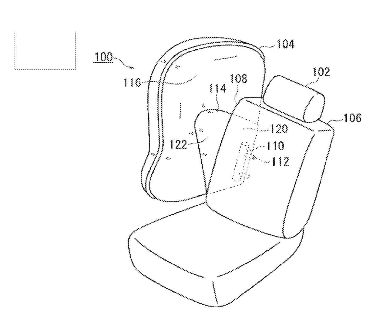
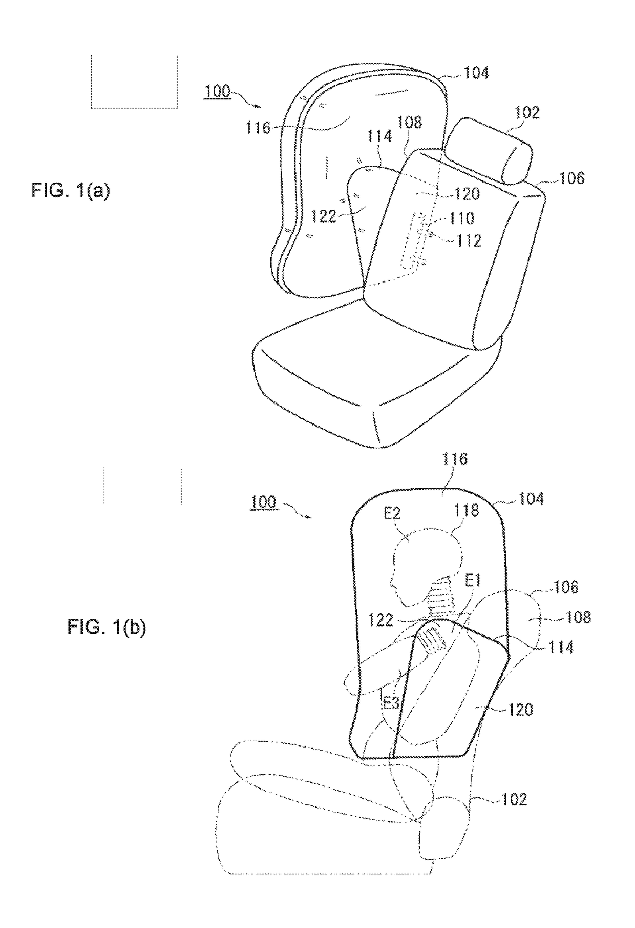
[0028]FIGS. 1(a) and (b) are diagrams illustrating a side airbag device according to the present invention (hereinafter, a side airbag 100). FIG. 1(a) is a perspective view illustrating, from above on an inner side in a vehicle width direction, the side airbag 100 and a seat 102 on a right side of the vehicle to which the side airbag 100 is applied. As illustrated in FIG. 1(a), the side airbag 100 is configured to inflate and deploy at the side of the seat 102.

[0029]A cushion 104 is a bag-like portion which restrains an occupant during an emergency such as an impact to the vehicle and which inflates and deploys in a flat shape between the occupant and a side door. The cushion 104 is formed by overlapping a plurality of sheets of a base fabric which constitute a surface of the cushion 104 with each other and sewing or bonding together the plurality of sheets of the base fabric. The cushion 104 is packaged into in a housing (not illustrated) provided in a side part 108 of a seat back ...

second embodiment

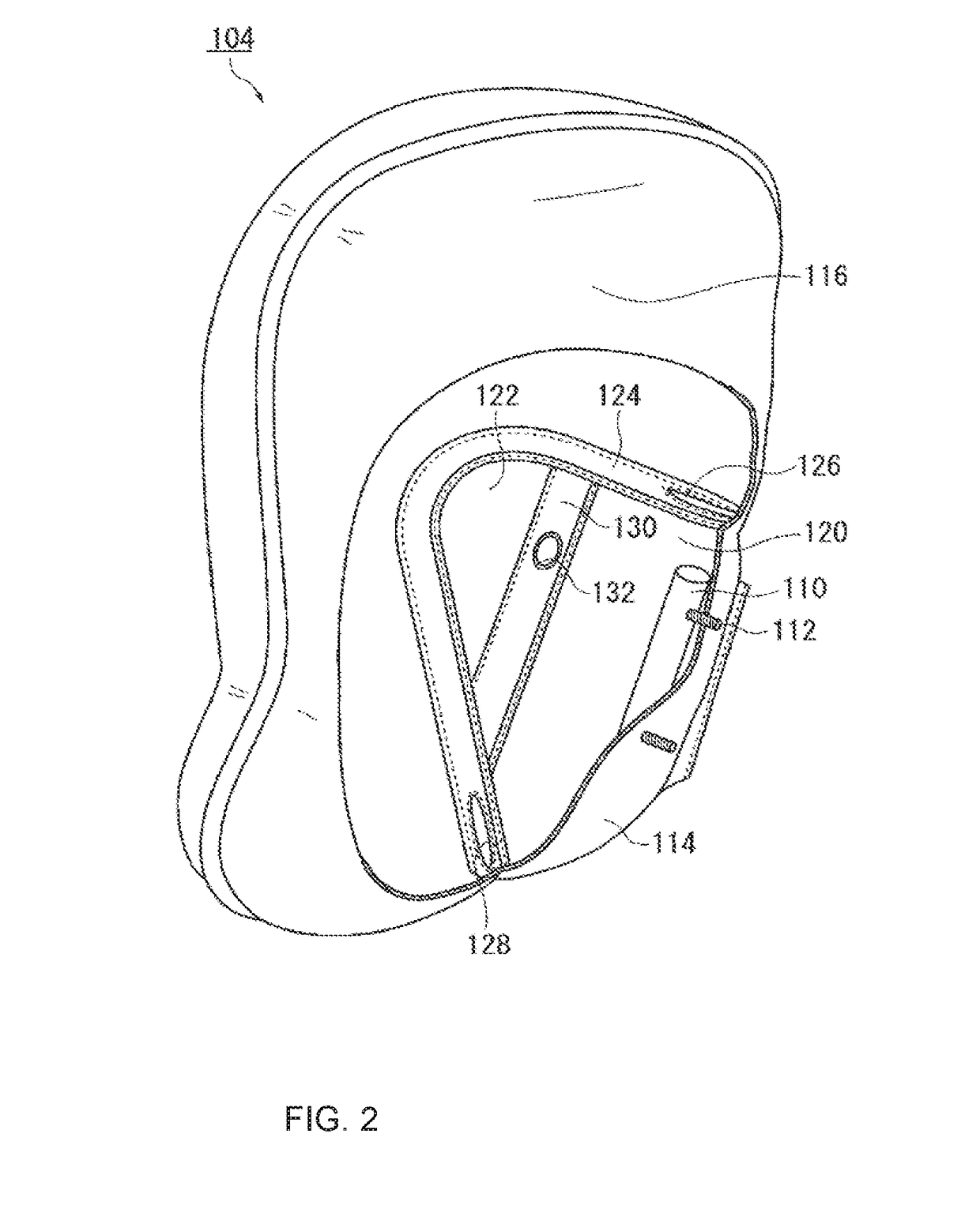
[0047]FIG. 5 is a diagram illustrating a side airbag device according to the present invention (hereinafter, a side airbag 200). In correspondence with FIG. 2, FIG. 5 illustrates an internal configuration of a cushion 202 by cutting away a part of a surface thereof. The side airbag 200 differs from the side airbag 100 shown in FIG. 2 in that an inner bag 204 is provided inside the rear chamber 114. Moreover, hereinafter, a description of a component similar to those described with reference to FIGS. 1 to 4 will be omitted by denoting the component using a similar reference sign.

[0048]The inner bag 204 is a bag-like portion arranged inside the rear chamber 114 and is structured such that upper and lower ends thereof penetrate into the front chamber 116. The inflator 110 is contained in the inner bag 204. Therefore, the inner bag 204 is configured to receive gas from the inflator 110 prior to the rear chamber 114. In the present embodiment, by receiving gas by the inner bag 204 and di...


PUM


Abstract

A side airbag device having a plurality of chambers. The side airbag 100 includes: an inflator 110; a rear chamber 114 which deploys at a side part 108 of a seat back 106 and a middle restraining part 122 that protrudes toward the front of a vehicle and a main part 120 at a rear side. A sectioning wall 124 which constitutes a front edge and an upper edge of the rear chamber 114. A front chamber 116 inflates into areas toward the front of the vehicle and the upper part of the vehicle from the sectioning wall 124. An upper opening 126 is formed on the sectioning wall 124 in a rear part of the upper edge of the rear chamber 114. A lower opening 128 is formed on the sectioning wall 124 in a lower part of the front edge of the rear chamber 114.

Description

CROSS REFERENCE TO RELATED APPLICATIONS[0001]This application claims priority to Japanese Patent Application No. 2014-148459, filed on Jul. 22, 2014 and PCT / JP2015 / 063923, filed on May 14, 2015.FIELD OF THE INVENTION[0002]The present invention relates to a side airbag device which restrains an occupant of a vehicle seat from a side impact applied to a vehicle or the like.BACKGROUND[0003]Airbags have almost become standard equipment in modern motor vehicles. An airbag is a safety device which operates during an emergency such as a vehicle collision and which inflates and deploys under gas pressure to engage with and protect an occupant. Airbags come in various types in accordance with installation locations or applications. For example, a front driver airbag device is provided at a center of a steering wheel in order to protect a driver from a collision in a longitudinal direction (i.e. frontal impact). In addition, in order to protect an occupant from a side collision or from a subs...

Claims


Application Information

Patent Timeline
IPC IPC(8): B60R21/231B60R21/233B60R21/207
CPCB60R21/23138B60R21/207B60R2021/23324B60R2021/23146B60R21/233B60R2021/0058B60R21/239
Inventor TAGUCHI, HIROYUKINAKAJIMA, YUTAKAFUKUDA, HIDEHONOGAMI, MITSUOKOBAYASHI, YUTOFUMA, MAKOTO
Owner AUTOLIV DEV AB
Why Eureka
Try Eureka