Light source device and projector

a light source device and projector technology, applied in semiconductor devices, lighting and heating apparatus, instruments, etc., can solve the problems of distortion aberration or spherical aberration, the efficiency of fluorescent light capture by illumination optical systems and projection optical systems, and the wavelength conversion efficiency falls, so as to limit the decrease in wavelength conversion efficiency and limit the effect of capturing fluorescent light efficiency

Active Publication Date: 2017-07-13
SHARP NEC DISPLAY SOLUTIONS LTD
View PDF2 Cites 17 Cited by
  • Summary
  • Abstract
  • Description
  • Claims
  • Application Information

AI Technical Summary

Benefits of technology

[0024]It is an object of the present invention to provide a light source device and a projector that can solve the above-described problems, that can reliably irradiate excitation light at an appropriate size, and that can limit any decrease in the wavelength conversion efficiency or can limit any decrease in the efficiency of capturing fluorescent light through an illumination optical system or a projection optical system.
[0028]a reducing optical system that reduces a luminous flux diameter of the excitation light that is supplied from the excitation light source; and

Problems solved by technology

When the irradiation size of the excitation light diverges from the appropriate size, satisfying the previously described first limitation or second limitation becomes problematic, and the problem therefore arises that the wavelength conversion efficiency falls and the efficient capture of fluorescent light by the illumination optical system and projection optical system decreases.
In addition, in the light source devices described in Patent Documents 1 and 2, aberration (in particular, distortion aberration or spherical aberration) occurs because luminous flux is bent greatly in lenses on the side close to the excitation light source (blue LD array), i.e., a lens on the side of the light source has high power, and moreover, has a high index of refraction.
This aberration that occurs in lenses on the light source side is difficult to correct by later-stage optical systems.
As a result, distortion aberration causes distortion in the light source image (the image of the blue LD array) that is formed in the phosphor region (phosphor layer), and spherical aberration causes nonuniformity of the intensity distribution of the excitation light by blurring of portions of the light source image.
When the intensity distribution of the excitation light is uneven, a phenomenon such as saturation occurs in portions of high light intensity, resulting in a decrease of wavelength conversion efficiency.

Method used


Image

  • Light source device and projector
  • Light source device and projector
  • Light source device and projector

Examples


Embodiment Construction

[0053]An exemplary embodiment of the present invention is next described with reference to the accompanying drawings.

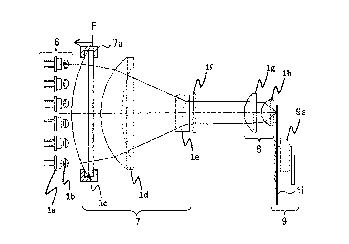
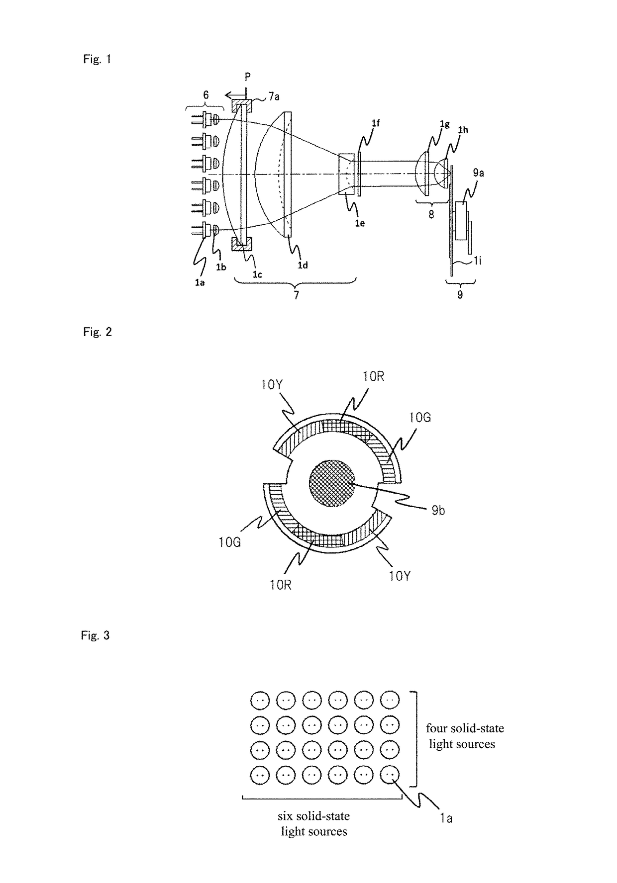
[0054]FIG. 1 is a schematic view showing the configuration of a light source device according to an exemplary embodiment of the present invention.

[0055]Referring to FIG. 1, the light source device includes solid-state light source unit 6 that is the excitation light source, reducing optical system 7, condensing optical system 8, diffuser 1f, and phosphor unit 9.

[0056]Solid-state light source unit 6 includes a plurality of solid-state light sources 1a and a plurality of collimator lenses 1b. Solid-state light sources 1a are, for example, blue laser diodes (LD) that supply blue light having peak wavelength in the blue wavelength band. Here, 24 blue LDs are arranged in 6×4 matrix form. However, the number of blue LDs is not limited to 24. The number of blue LDs may be increased or decreased as necessary.

[0057]Collimator lenses 1b are provided for each of solid-state ligh...


PUM


Abstract

A light source device includes: a phosphor unit that is provided with a phosphor; an excitation light source that supplies excitation light that excites the phosphor; a reducing optical system that reduces the luminous flux diameter of the excitation light; and a light condensing optical system that condenses, on the phosphor unit, excitation light for which the luminous flux diameter was reduced by the reducing optical system. The reducing optical system includes: a plurality of lenses including two lenses having positive power; and a lens-moving section that moves the lens back and forth along the direction of the optical axis. The lens is disposed on the excitation light source side, and has a lower power than the lens. The refractive index of the lens is equal to or smaller than the refractive indexes of the other lenses of the reducing optical system.

Description

TECHNICAL FIELD[0001]The present invention relates to a light source device that is equipped with a phosphor and to a projector that uses the light source device.BACKGROUND ART[0002]Although high-luminance projectors are provided that take mercury lamps as a light source, mercury lamps contain mercury, a hazardous material, and taking into consideration the impact upon the environment, there is consequently an urgent need for the development of mercury-free products. Against this background, the development of LEDs (Light Emitting Diodes) and LDs (Laser Diodes) has been advanced, and low-luminance LED projectors and laser projectors that take these devices as light sources are already being introduced into the marketplace.[0003]However, because high-luminance green LEDs or compact, high-output green LDs are not yet being mass-produced, a high-luminance LED projector or laser projector has not yet been introduced to the market.[0004]In response, high-luminance projectors that use a p...

Claims


Application Information

Patent Timeline
Patent Type & Authority Applications(United States)
IPC IPC(8): G03B21/20G03B21/14F21V5/00F21K9/64F21V9/16F21V9/40
CPCG03B21/204F21K9/64F21Y2115/30F21V5/007G03B21/142F21V9/16G03B21/2013G03B21/2033F21V9/30
Inventor MATSUBARA, MASATERU
Owner SHARP NEC DISPLAY SOLUTIONS LTD
Why Eureka
Try Eureka