MEMS Valve Actuator System and Method

a technology of valve actuator and actuator, which is applied in the field of mems valve actuator system and method, can solve the problems of slow progress of actuation system, limited use of above techniques, and many limitations of one-size valves, and achieve the effect of minimizing the impact

Active Publication Date: 2017-11-02
BARRETT JR RAYMOND LOUIS
View PDF6 Cites 2 Cited by
  • Summary
  • Abstract
  • Description
  • Claims
  • Application Information

AI Technical Summary

Benefits of technology

[0018]In another aspect the outer side of said cell body has a permanent shaped curvature while the inner side shape is adjusted by the pre-determined length of the inner strings or structures connecting both ends. In yet another aspect a space location component is used to establish and update the position of the apparatus above the datum or ground, and local sensors are used to establish component orientation and based on the expected point of contact of the component with said datum or ground and / or the impact from another body sensed through an accelerometer, the valve is operated as to minimize impact effects. In one aspect one or more of said apparatuses are mounted along the inside of a helmet. In another aspect one or more fluid refill components are connected to said one or more cells inlet port in order to recharge the system when fluid is expended. In yet another aspect one or more of said apparatuses are mounted along the inside of a body padding. In one aspect one or more fluid refill components are connected to said one or more cells in order to recharge the system when fluid is expended.

Problems solved by technology

Modern systems have benefited by the propagation of miniaturization into the realms of computation, communications, and sensing, but miniaturization has been slower in progress in actuation systems.
However, many of these suffer the limitation of being a ‘one-size-fits-all’ solution to a problem that demands customization.
The use of the above techniques is usually limited to the prediction of brain reaction to recovery from injuries and / or reaction to care protocols.

Method used


Image

  • MEMS Valve Actuator System and Method
  • MEMS Valve Actuator System and Method
  • MEMS Valve Actuator System and Method

Examples


Embodiment Construction

[0033]To provide an overall understanding of the invention, certain illustrative embodiments and examples will now be described. However, it will be understood by one of ordinary skill in the art that the same or equivalent functions and sequences may be accomplished by different embodiments that are also intended to be encompassed within the spirit and scope of the disclosure. The compositions, apparatuses, systems and / or methods described herein may be adapted and modified as is appropriate for the application being addressed and that those described herein may be employed in other suitable applications, and that such other additions and modifications will not depart from the scope hereof.

[0034]Simplifications or omissions may be made to avoid obscuring the purpose of the section. Such simplifications or omissions are not intended to limit the scope of the present invention. All references, including any patents or patent applications cited in this specification are hereby incorpo...


PUM


Abstract

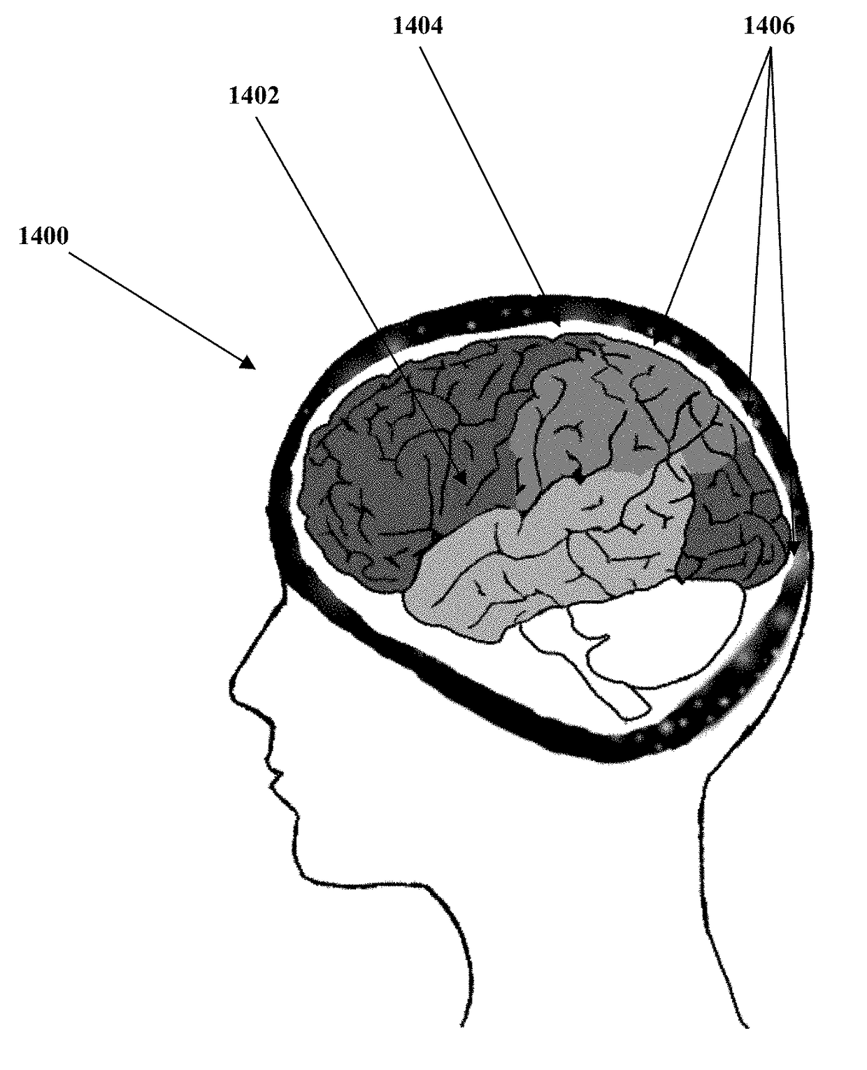
A micro-electro-mechanical (MEMS) exhaust valve-based impact attenuating fluid filled cell for use in cushioning impact and decelerating of a wearer's body portion (e.g. head, shoulder, torso, etc.) after an impact. In combination with the use of accelerometers, pressure sensors, location and other electronics supply signals to a microcontroller, the controlled opening / closing of said exhaust valve (resulting in the expelling of said fluids with an optional combination with cell refill means) when certain parameters exceed a threshold. Individuals who engage in activities that carry a risk of injury to the head from impact in the normal course of the activity could, in combination with regular exams, benefit from a system that produces and updates a kinematic 3D model of the individual's head, including brain matter, cerebrospinal fluid paths, arterial and venous blood flow pathways, as well as the skull, supporting connective tissues and other biological structures in the head suitable for interaction with exogenous stimuli prepared from hypothetical or actual recorded impact events.

Description

CROSS-REFERENCE TO RELATED APPLICATIONS[0001]This application is a divisional of pending U.S. application. “MEMS VALVE ACTUATOR SYSTEM”, Ser. No. 14 / 469,609, filed Aug. 27, 2014, the disclosure of which is incorporated herein by reference in its entirety.CROSS-REFERENCE TO RELATED APPLICATIONS[0002]This application claims priority to co-pending U.S. Provisional patent applications; Ser. No. 61 / 870,111 titled “MEMS Valve Actuator System”, filed on Aug. 26, 2013; Ser. No. 61 / 878,008 titled “Personalized Head Model-Base System MEMS Valve Actuator System”, filed on Sep. 15, 2013; Ser. No. 61 / 887,395 titled “Pressurized Protection Pads”, filed on Oct. 6, 2013 and Ser. No. 61 / 896,555 titled “Impact Attenuating Pad Control System”, filed on Oct. 28, 2013; the disclosures of which are herein incorporated by reference in their entirety.PATENTS AND SUPPORTED DOCUMENTS CITED[0003]The following patent documents and references are incorporated by reference in their entirety, D. T. Branson et al,...

Claims


Application Information

Patent Timeline
Patent Type & Authority Applications(United States)
IPC IPC(8): A42B3/12A42B3/28A61B5/00F16K31/00
CPCA61B5/4064A42B3/281F16K31/004A42B3/122F16K99/0048F16K2099/0082A42B3/121A61B5/002A61B5/1114A61B5/6803A61B2503/10A61B2562/0219A61B2562/04
Inventor BARRETT, JR., RAYMOND LOUIS
Owner BARRETT JR RAYMOND LOUIS
Why Eureka
Try Eureka