Coaxial connector with plunger

Active Publication Date: 2017-12-28
HOLLAND ELECTRONICS
View PDF0 Cites 0 Cited by
  • Summary
  • Abstract
  • Description
  • Claims
  • Application Information

AI Technical Summary

Benefits of technology

The patent text describes a way to prevent unwanted signals from interfering with electrical connections. This is done by using a cover that blocks out radio frequency signals. These covers are made of metal or conductive material to reduce or prevent the transfer of electromagnetic signals. The technical effect of this invention is to improve the accuracy and reliability of electrical connectors by eliminating interference from extraneous signals.

Problems solved by technology

For example, where the connector is a splice and terminates an active coaxial cable, problems of extraneous signal transfer may arise.
The radiated signal may be received by other radio frequency equipment and adversely affect that equipment's performance.
These received signals may adversely affect the radio frequency equipment interconnected by the splice.

Method used


Image

  • Coaxial connector with plunger
  • Coaxial connector with plunger
  • Coaxial connector with plunger

Examples


Embodiment Construction

[0019]The disclosure provided in the following pages describes examples of some embodiments of the invention. The designs, figures, and description are non-limiting examples of the embodiments they disclose. For example, other embodiments of the disclosed device and / or method may or may not include the features described herein. Moreover, described features, advantages or benefits may apply to only certain embodiments of the invention and should not be used to limit the disclosed invention.

[0020]As used herein, the term “coupled” includes direct and indirect connections. Moreover, where first and second devices are coupled, intervening devices including active devices may be located therebetween.

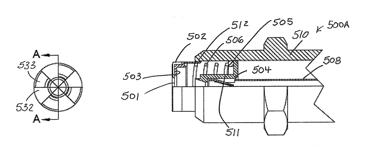
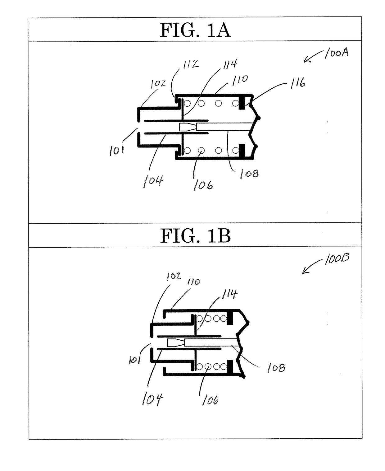
[0021]FIGS. 1A-B show a female coaxial connector with moving plunger assembly or nose 100A-B.

[0022]In particular, FIG. 1A shows a female coaxial cable connector such as an F-Type connector. A case or body 110 houses a plunger 104, a spring 106, and a center pin 108. Here and elsewhere in thi...


PUM


Abstract

An electrical connector for use with coaxial cables includes a plunger urged to protrude from a case by a spring.

Description

PRIORITY CLAIM AND INCORPORATION BY REFERENCE[0001]This application is a CIP of Ser. No. 15 / 482,727 filed Apr. 8, 2017 which is a continuation of Ser. No. 14 / 488,202 filed Sep. 16, 2014, now U.S. Pat. No. 9,627,814, which is a CIP of Ser. No. 13 / 913,487 filed Jun. 9, 2013, now U.S. Pat. No. 9,136,629, which is a CIP of Ser. No. 13 / 911,032 filed Jun. 5, 2013, now U.S. Pat. No. 9,130,288, which claims the benefit of provisional application 61 / 717,595 filed Oct. 23, 2012 and the benefit of provisional application 61 / 673,356 filed Jul. 19, 2012. This application is a CIP of Ser. No. 15 / 644,734 filed Jul. 7, 2017 which is a CIP of Ser. No. 14 / 957,179 filed Dec. 2, 2015, now U.S. Pat. No. 9,711,919, which is a CIP of Ser. No. 14 / 588,889 filed Jan. 2, 2015, now U.S. Pat. No. 9,246,275, which is a CIP of Ser. No. 14 / 069,221 filed Oct. 31, 2013, now U.S. Pat. No. 9,178,317, which is a CIP of Ser. No. 13 / 712,828, filed Dec. 12, 2012, now abandoned, which claims the benefit of provisional appl...

Claims


Application Information

Patent Timeline
IPC IPC(8): H01R13/6581H01R24/52H01R13/08H01R13/453H01R24/54H01R103/00
CPCY10T29/49208H01R24/525H01R13/4538H01R13/08H01R24/54H01R13/6581H01R2103/00H01R13/17
Inventor HOLLAND, MICHAEL
Owner HOLLAND ELECTRONICS
Why Eureka
Try Eureka