
Optical imaging lens
a technology of optical imaging and lens, applied in the field of optical imaging lenses, can solve the problems of difficult reduction of the length of the telephoto lens, the design of the optical imaging lens cannot produce an optical imaging lens having both imaging quality and small size, and the need for good optical performan
- Summary
- Abstract
- Description
- Claims
- Application Information
AI Technical Summary
Benefits of technology
Problems solved by technology
Method used
Image

Examples
first embodiment
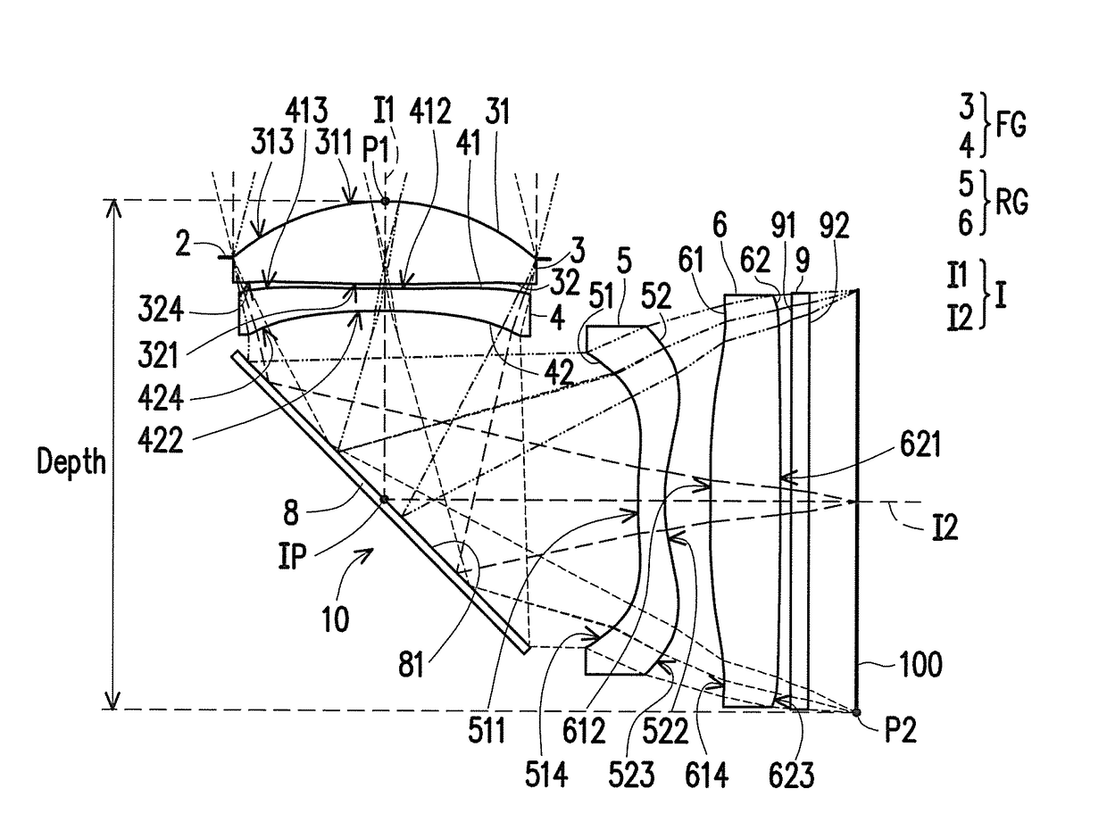
[0079]Moreover, the relationship between each of the important parameters in the optical imaging lens 10 of the first embodiment is as shown in FIG. 38.
[0080]wherein,
[0081]T1 is the thickness of the first lens element 3 on the optical axis I, i.e., on the first optical axis I1;
[0082]T2 is the thickness of the second lens element 4 on the optical axis I, i.e., on the first optical axis I1;
[0083]T3 is the thickness of the third lens element 5 on the optical axis I, i.e., on the second optical axis I2;
[0084]T4 is the thickness of the fourth lens element 6 on the optical axis I, i.e., on the second optical axis I2;
[0085]TF is the thickness of the filter 9 on the optical axis I, i.e., on the second optical axis I2;
[0086]G12 is the distance from the image-side surface 32 of the first lens element 3 to the object-side surface 41 of the second lens element 4 on the optical axis I, i.e. an air gap from the first lens element 3 to the second lens element 4 on the first optical axis I1;
[0087]G...
second embodiment
[0117]The detailed optical data of the optical imaging lens 10 is as shown in FIG. 12, and in the second embodiment, the EFL of the optical imaging lens 10 is 10.025 mm, the HFOV thereof is 14.069°, the Fno thereof is 2.800, the TTL thereof is 9.285 mm, the ImaH thereof is 2.517 mm, the fFG thereof is 8.456 mm, and the Depth thereof is 6.043 mm.
[0118]FIG. 13 shows each of the aspheric coefficients of the object-side surfaces 31, 41, 51, and 61 and the image-side surfaces 32, 42, 52, and 62 of the second embodiment in general formula (1).
[0119]Moreover, the relationship between each of the important parameters in the optical imaging lens 10 of the second embodiment is as shown in FIG. 38.
[0120]In the longitudinal spherical aberration figure of FIG. 11A of the second embodiment in the condition that the pupil radius thereof is 1.8000 mm, the imaging point deviation of off-axis rays at different heights is controlled to be within the range of ±40 microns. In the two field curvature fig...
third embodiment
[0123]The detailed optical data of the optical imaging lens 10 is as shown in FIG. 16, and in the third embodiment, the EFL of the optical imaging lens 10 is 10.079 mm, the HFOV thereof is 14.008°, the Fno thereof is 2.801, the TTL thereof is 9.434 mm, the ImaH thereof is 2.517 mm, the fFG thereof is 8.51 mm, and the Depth thereof is 5.920 mm.
[0124]FIG. 17 shows each of the aspheric coefficients of the object-side surfaces 31, 41, 51, and 61 and the image-side surfaces 32, 42, 52, and 62 of the third embodiment in general formula (1).
[0125]Moreover, the relationship between each of the important parameters in the optical imaging lens 10 of the third embodiment is as shown in FIG. 38.
[0126]In the longitudinal spherical aberration figure of FIG. 15A of the third embodiment in the condition that the pupil radius thereof is 1.8000 mm, the imaging point deviation of off-axis rays at different heights is controlled to be within the range of ±37 microns. In the two field curvature figures ...
PUM
 Abstract
Description
Claims
Application Information