Backlight module and display device

Active Publication Date: 2018-04-19
TCL CHINA STAR OPTOELECTRONICS TECH CO LTD
View PDF0 Cites 1 Cited by
  • Summary
  • Abstract
  • Description
  • Claims
  • Application Information

AI Technical Summary

Benefits of technology

[0017]The reflecting collimator lens of the backlight module can reflect a light emitted from the LED lamp to the color polarizing layer with an approximately vertical angle. Because the light entering the color polarizing layer is

Problems solved by technology

When an LED adopting the yellow YAG phosphor matches with the liquid crystal panel, the

Method used


Image

  • Backlight module and display device

Examples


Embodiment Construction

[0020]The following content combines with the drawings and the embodiment for describing the present invention in detail.

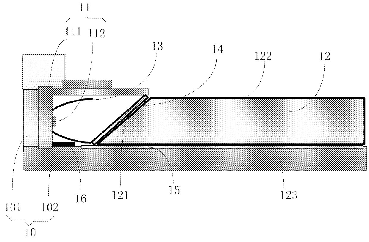
[0021]With reference to FIG. 1, the present invention provides a backlight module and a display device having the same (not shown in the FIGURE). The display device further includes a liquid crystal panel, and the liquid crystal panel is installed on the backlight module. In the present embodiment, the backlight module includes a plastic frame 10, a backlight source 11 and a light guide plate 12. The backlight source 11 and the light guide plate 12 are received in the plastic frame 10. The light guide plate 12 includes a light incident surface 121 and a light emitting surface 122. The backlight source 11 includes a circuit board 111, a reflecting collimator lens 13 fixed to the circuit board 111 and a LED lamp 112 disposed inside the reflecting collimator lens 13.

[0022]The reflecting collimator lens 13 includes a parabolic reflecting surface 131. The LED lamp is l...


PUM


Abstract

The present invention provides a backlight module. The backlight module includes a plastic frame, a backlight source and a light guide plate. The backlight source and the light guide plate are received in the plastic frame. The light guide plate includes a light incident surface and a light emitting surface. The backlight source includes a circuit board, a reflecting collimator lens fixed to the circuit board and a LED lamp disposed inside the reflecting collimator lens. The reflecting collimator lens includes a parabolic reflecting surface, and the LED lamp is located at a center location of the parabolic reflecting surface. The light incident surface is covered with a color polarizing layer, and the parabolic reflecting surface faces toward the color polarizing layer. The present invention also discloses a display device.

Description

CROSS REFERENCE[0001]The claims of this application have submitted to the State Intellectual Property Office of the People's Republic of China (SIPO) on Apr. 22, 2016, Application No. 201610256089.7. The priority right based on the China application has a title of “Backlight module and display device”. The entire contents of the above-mentioned patent application will be incorporated in the present application through citing.FIELD OF THE INVENTION[0002]The present invention relates to a liquid crystal display technology field, and more particularly to a backlight module and a display device.BACKGROUND OF THE INVENTION[0003]A liquid crystal display device is a main flat display technology in the current market. The display device requires a backlight as a light source to illuminate the liquid crystal display device. A conventional backlight module includes a backlight source formed by LED. A light emitted from the backlight source become a surface light source and emitting out throug...

Claims


Application Information

Patent Timeline
IPC IPC(8): F21V8/00G02B5/20
CPCG02B6/0026G02B6/0031G02B6/0056G02B6/0073G02B6/002G02B5/207G02F1/133603G02F1/133609G02F1/133615G02F1/13362G02F1/133621G02B27/30G02B19/0014G02B19/0061G02B6/0023
Inventor FAN, YONG
Owner TCL CHINA STAR OPTOELECTRONICS TECH CO LTD
Why Eureka
Try Eureka