Piezoelectric Pump

Active Publication Date: 2009-06-04
MURATA MFG CO LTD
View PDF2 Cites 11 Cited by
  • Summary
  • Abstract
  • Description
  • Claims
  • Application Information

AI Technical Summary

Benefits of technology

[0025]In order to match the inversion plane of the piezoelectric element alone with the neutral plane of the entire diaphragm, the thickness of a portion of the piezoelectric element at a side of the inversion plane separated from the diaphragm can be increased compared with the thickness of a portion of the piezoelectric element at the other side of the inversion plane adjacent to the diaphragm, or the number of laminated piezoelectric layers separated from the diaphragm can be increased compared with the number of laminated piezoelectric layers adjacent to the diaphragm in the piezoelectric element. Moreover, the inversion plane of the piezoelectric element alone can match the neutral plane of the entire diaphragm without shifting the position of the inversion plane of the piezoelectric element alone from the middle position of the piezoelectric element to the diaphragm in some cases. That is, the strength of an electric field of a driving voltage applied to the piezoelectric layer separated from the diaphragm can be increased compared with the strength of an electric field of a driving voltage applied to the piezoelectric layer adjacent to the diaphragm in the piezoelectric element, or the degree of polarization of the piezoelectric layer separated from the diaphragm can be increased compared with the degree of polarization of the piezoelectric layer adjacent to the diaphragm in the piezoelectric element.
[0026]According to the present invention, a large displacement can be achieved at the central portion of a piezoelectric element even when the piezo

Problems solved by technology

This leads to stable operati

Method used


Image

  • Piezoelectric Pump
  • Piezoelectric Pump
  • Piezoelectric Pump

Examples


first embodiment

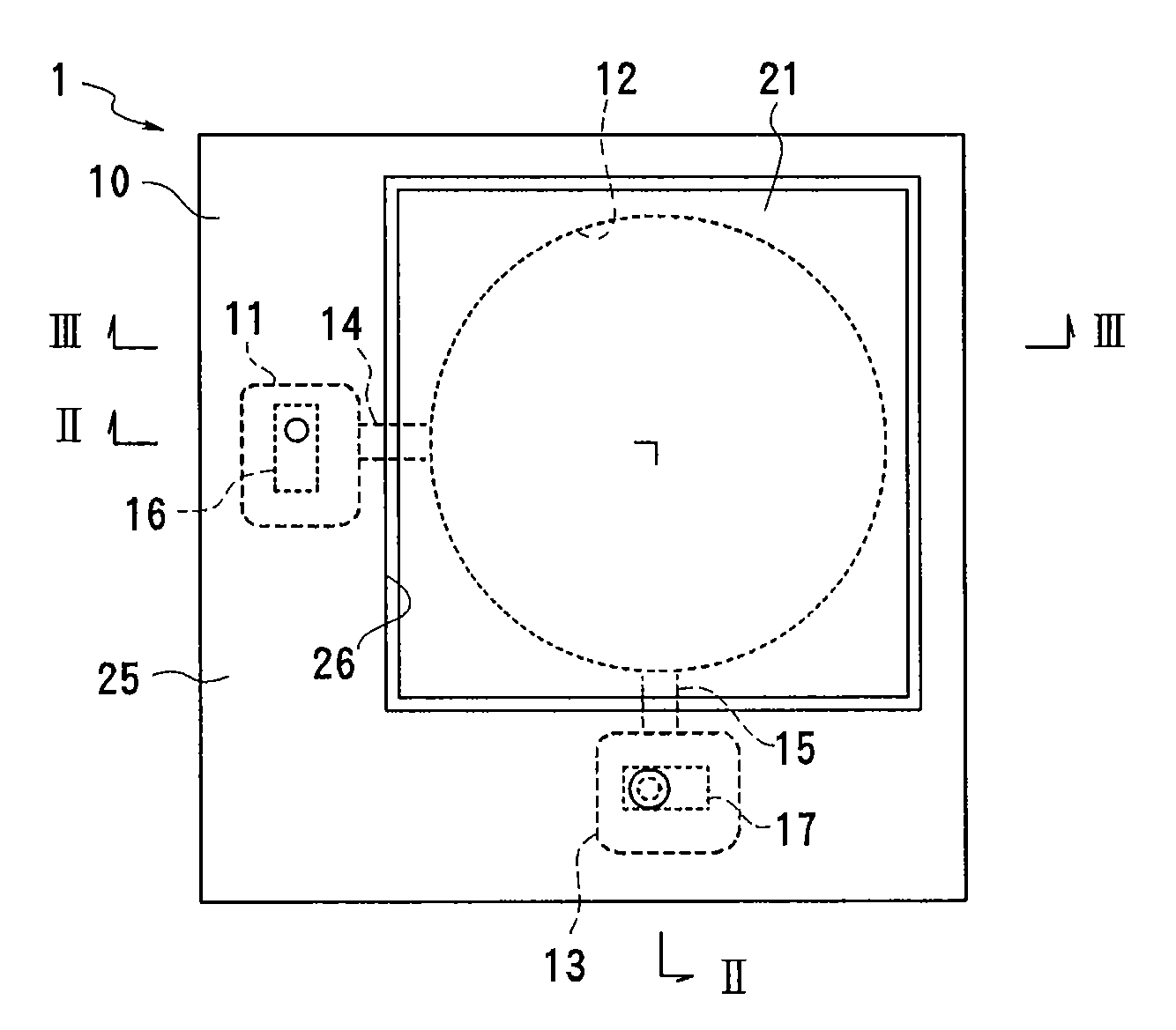
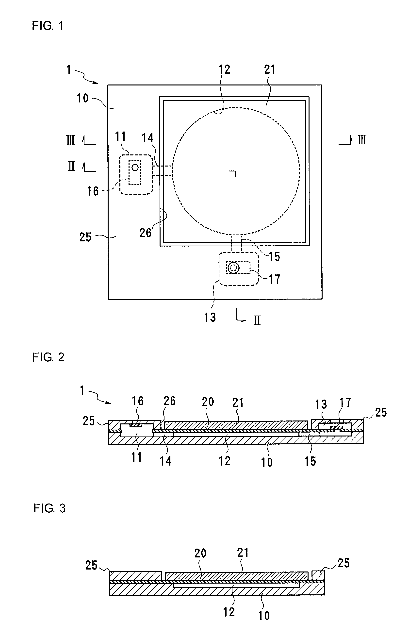
[0069]A piezoelectric pump according to a first embodiment of the present invention will now be described with reference to FIGS. 1 to 3. FIG. 1 is a plan view illustrating the entire piezoelectric pump. FIG. 2 is a cross-sectional view taken along line II-II in FIG. 1. FIG. 3 is a cross-sectional view taken along line III-III in FIG. 1.

[0070]This piezoelectric pump 1 includes a pump body 10, a diaphragm 20, a piezoelectric element 21, and a retaining plate 25. The pump body 10 is composed of metal or a high-rigidity material such as resin. An inlet valve chest 11, a pump chamber 12, and an outlet valve chest 13 are formed between the pump body 10 and the retaining plate 25, and are connected to each other via connecting channels 14 and 15. An inlet check valve 16 is disposed in the inlet valve chest 11. The inlet check valve 16 allows passage of fluid flowing from an inlet port to the inlet valve chest 11, and blocks fluid flowing in the opposite direction. An outlet check valve 17...

second embodiment

[0081]FIGS. 10 to 13 illustrate a piezoelectric element according to a second embodiment. This piezoelectric element 30 is a laminate including a plurality of (herein eight) piezoelectric layers 31a to 31h each having an electrode of one of the three electrode patterns shown in FIGS. 6(a) to 6(c). The order of the electrode patterns is 6(b), 6(a), 6(b), 6(a), 6(b), 6(c), 6(b), 6(c), and 6(b) from the top. That is, continuous electrodes and split electrodes are alternately disposed in a direction along which the layers are stacked.

[0082]The piezoelectric layers 31a to 31h are polarized as shown in FIG. 12. That is, the polarization direction in the central area and that in the peripheral area of each of the piezoelectric layers 31a to 31h are opposite to each other. When the piezoelectric layers 31a to 31h are sectioned into a first piezoelectric portion and a second piezoelectric portion whose expansion / contraction directions differ from each other and the border is defined as Fp, t...

third embodiment

[0084]FIGS. 14 and 16(a) to 16(c) illustrate another example of a specific structure of a piezoelectric element. This piezoelectric element 40 includes two laminated piezoelectric layers 41a and 41b composed of a piezoelectric ceramic as that in the first embodiment. That is, the piezoelectric ceramic layers 41a and 41b in a state of two green sheets are laminated and pressed with an interlayer electrode 42 interposed therebetween. The laminate is then fired, and polarized after electrodes 43 and 44 are formed on the top and bottom surfaces. FIG. 16(a) illustrates an electrode pattern on the top surface, FIG. 16(b) illustrates an electrode pattern of the interlayer electrode, and FIG. 16(c) illustrates an electrode pattern on the bottom surface.

[0085]The interlayer electrode 42 includes a circular continuous electrode portion 42a and dummy electrode portions 42b formed at four corners around the continuous electrode portion. The circular continuous electrode portion 42a extends to o...


PUM


Abstract

A piezoelectric pump capable of generating a large displacement at a central portion of a piezoelectric element even when a driving voltage is relatively low and preventing short-circuits caused by migration. The piezoelectric pump includes a pump body with a pump chamber, and a piezoelectric element that closes the pump chamber. The central area and the peripheral area of the piezoelectric element are bent in opposite directions by applying voltages to the piezoelectric element so that the volume of the pump chamber is changed. The piezoelectric element is a laminate including a plurality of piezoelectric layers with electrodes interposed therebetween. The central area and the peripheral area of each piezoelectric layer are polarized opposite to each other in the thickness direction, and the electrodes are formed such that voltages in the same direction in the thickness direction are applied to the central area and the peripheral area of each piezoelectric layer. Since voltages at the same potential are applied to the electrodes formed in the same planes of the piezoelectric layers, short-circuits caused by migration can be prevented.

Description

CROSS REFERENCE TO RELATED APPLICATIONS[0001]The present application is a continuation of International Application No. PCT / JP2007 / 063645, filed Jul. 9, 2007, which claims priority to Japanese Patent Application No. JP2006-190176, filed Jul. 11, 2006, the entire contents of each of these applications being incorporated herein by reference in their entirety.FIELD OF THE INVENTION[0002]The present invention relates to piezoelectric pumps, and more specifically, relates to piezoelectric pumps including piezoelectric elements to be bent.BACKGROUND OF THE INVENTION[0003]Piezoelectric pumps including pump bodies with pump chambers and piezoelectric elements fixed to the pump bodies so as to close openings of the pump chambers and bent by voltage application so as to change the volumes of the pump chambers are well known. Examples of such piezoelectric elements include unimorph cells and bimorph cells, and both types of cells have a disadvantage that they cannot achieve a sufficient discha...

Claims


Application Information

Patent Timeline
IPC IPC(8): F04B17/03F04B43/02F04B43/04F04B45/04F04B45/047
CPCF04B43/046H01L41/257H01L41/0973H01L41/083H01L41/0471H10N30/871H10N30/2047H10N30/50H10N30/045F04B53/10F05B2210/11Y10S417/00
Inventor HIRATA, ATSUHIKOKANAI, SHUNGOKAMITANI, GAKU
Owner MURATA MFG CO LTD
Why Eureka
Try Eureka