
Method and reactor for the non-thermal decomposition and pasteurization of organic process materials by electroporation

Inactive Publication Date: 2010-04-06
KERNFORSCHUNGSZENTRUM KARLSRUHE GMBH +1
View PDF10 Cites 12 Cited by
  • Summary
  • Abstract
  • Description
  • Claims
  • Application Information

AI Technical Summary

Benefits of technology

[0010]The invention solves the object to modify biological cells by means of pulsed electroporation in such a way that processing can take place on an industrial scale. That is, large volumes are processed in a reactor designed for that purpose and operated by the method with minimal energy consumption.
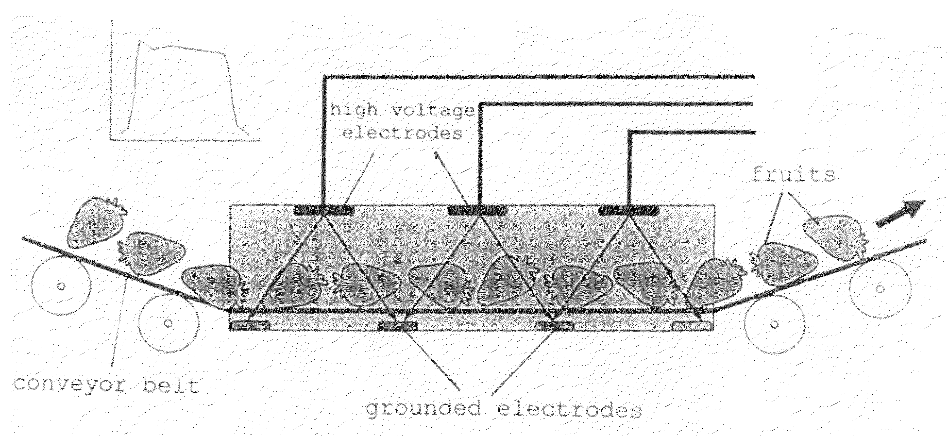
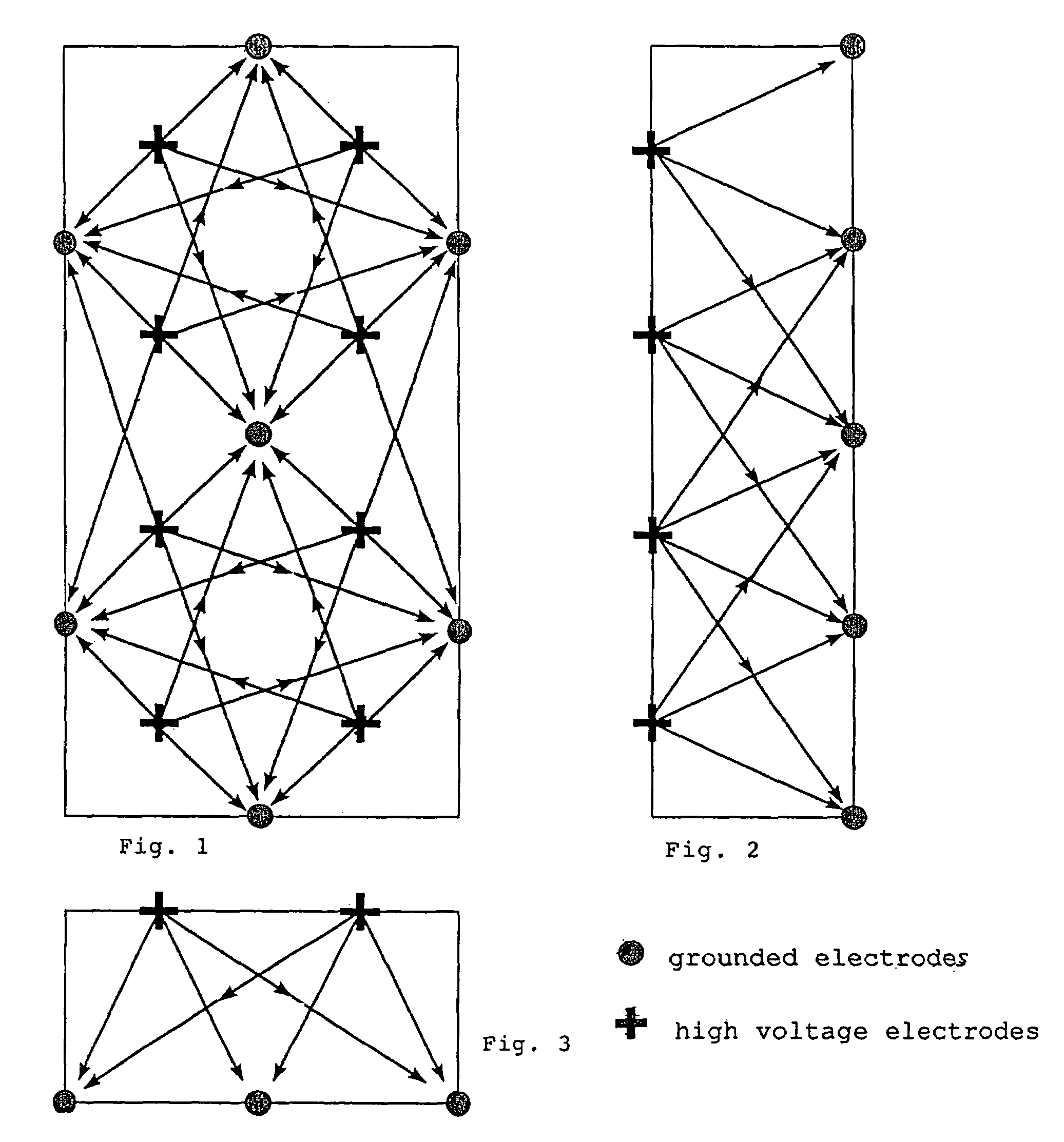
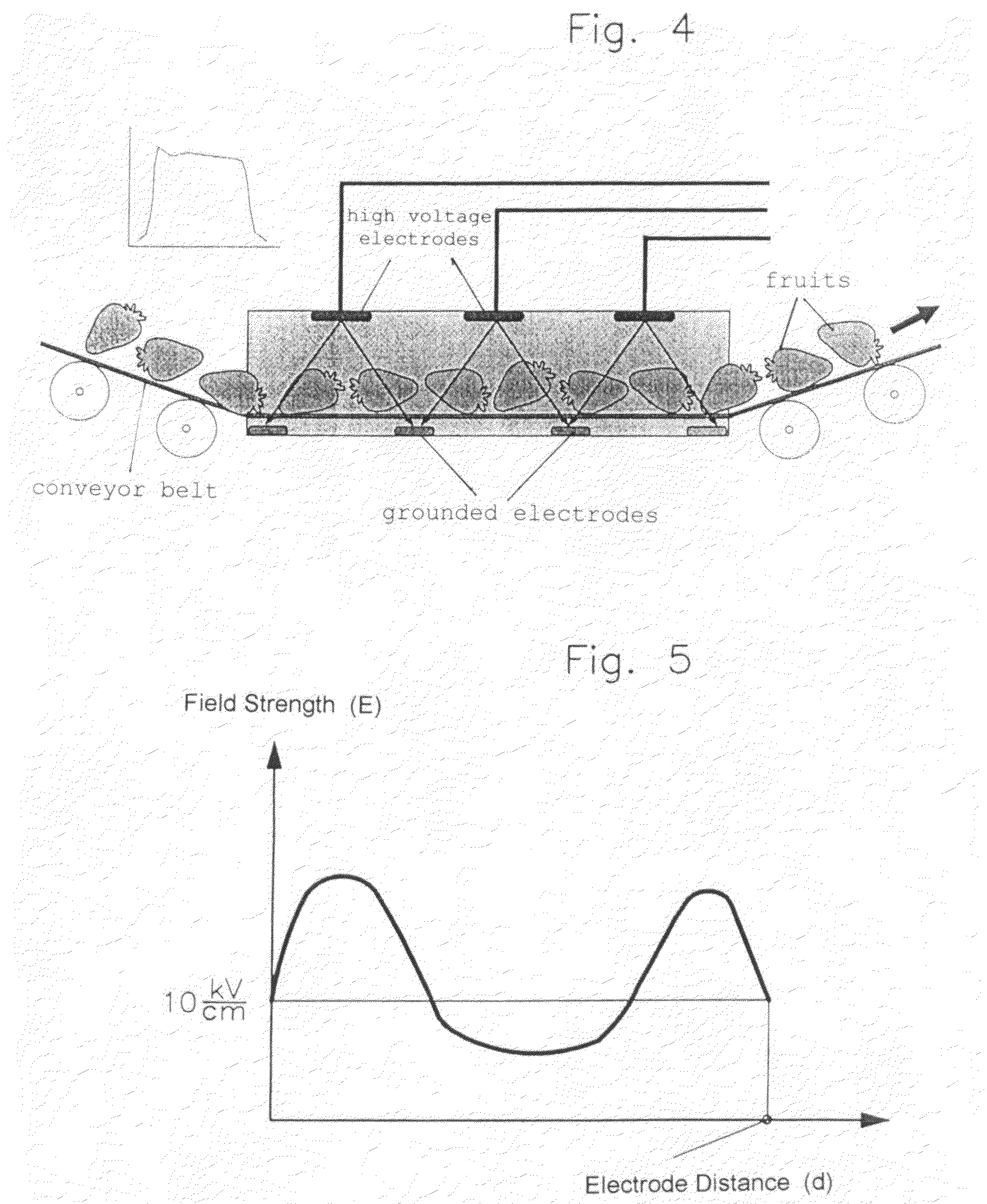
[0015]The electrode groups are energized by a high voltage subsequently, like in a running fire, with a time-dispersion corresponding up to a multiple pulse length such that the field is always generated by a single electrode group. The travel direction of the high voltage exposure area can be in the flow direction of the processed material or in the opposite direction but the electrode groups are statistically energized so that, based on the electrode arrangement, in the reactor from the entrance to the exit, the direction of the electric field strength E is constantly changed in the rhythm of the high voltage energization of the groups. It is essential that always only one electrode group is energized by high voltage. In this way, mutual field displacements and, consequently, areas with field lines extending normal to the flow axis, as they would occur with a concurrent energization of two or several electrode groups are avoided. Based on the length of the electrical action, the running fire direction is preferably in the flow direction of the process material since, then, the process material is exposed to the electrical action for a longer period as it moves in the same direction.
[0018]In addition to the effect of the field strength increase at the more distant grounded electrodes, the electric field strength is also increased in the nearby area by a factor 10. In this way, it is ensured that in the area of the more distant grounded electrodes, the cells material is reliably electroporated.
[0028]The sum of the surface areas of the high voltage electrodes exposed in the reactor is about the same as the sum of the surfaces of the adjacent grounded electrodes and is not substantially less if the next following grounded electrode is also taken into account. Herein, the electrode area is to be so dimensioned that the aspect ratio of the electrode surface area to the distance d between the respective high voltage electrode and the corresponding grounded electrodes do not exceed the value:F:d=½ cmThe electrolytic current density should be about equal. An even greater aspect ratio results in even more homogeneous field strength distributions but increases the electrolytic losses to a larger degree.
[0030]Concerning the treatment time, it has been found that, if the electrodes are so distributed over the respective longitudinal area that, in the projection of the longitudinal area with the high-voltage electrodes normal to the flow direction onto the longitudinal area of the grounded electrodes, the high voltage electrodes are disposed on a closed, simply curved line or a line section thereof about a grounded electrode (or also with a reversed projection), the treatment time can be substantially reduced.

Problems solved by technology

By compression, the outer pressure results in the rupture of the cells walls and the release of the cell content.
Both classical processes have grave disadvantages: The thermal treatment consumes a relatively large amount of energy and damages the cell content.
The mechanical compressing requires relatively expensive apparatus and the degree of the decomposition is generally lower than with thermal decomposition.

Method used


Image

  • Method and reactor for the non-thermal decomposition and pasteurization of organic process materials by electroporation
  • Method and reactor for the non-thermal decomposition and pasteurization of organic process materials by electroporation
  • Method and reactor for the non-thermal decomposition and pasteurization of organic process materials by electroporation

Examples


Embodiment Construction

[0043]Measurements with beets, oriented on the electric field generated in the reactor have shown that the specific energy, based on a beet, of 8 kJ can be reduced to about 2 kJ / kg if all the cells are involved in the electroporation. In addition to the incomplete electroporation in a tube arrangement, also the transport of whole fruits in the tube was found to be disadvantageous, since canting and wedging of the process material may occur which results in blockages that must be manually eliminated. Therefore the present invention prefers a material transport wherein a continuous transport force is applied to the fruits as this occurs for example in connection with a chain conveyor.

[0044]The through-put of a chain conveyor is determined by the conveyor speed, the width, the height and the degree of filling. Depending on the biological cell material, the height of the conveyor is about 50 cm; the transport speed is so adjusted that the specific energy supplied by the high voltage pul...


PUM

PropertyMeasurementUnit
Timeaaaaaaaaaa
Timeaaaaaaaaaa
Electric potential / voltageaaaaaaaaaa

Abstract

In a reaction chamber, which constitutes a component of a process installation for obtaining foodstuffs or foodstuff components, biological products in harvested form that are whole or in pieces are subjected to pulsed electric fields as they pass through said reaction chamber, said electric fields forming pores in the cell walls so as to irreversibly open the latter, thus making the content of the cells more easily accessible. This is achieved by electrode groups, which can be energized to a high voltage and are located in the wall of a longitudinal passage of the reactor through which the process material is moved past grounded electrodes located in an opposing longitudinal wall area. Each electrode group is connected to an electric energy accumulator such as for example, a Marx generator, by means of a switch, in order to rapidly establish electric fields of multiple directions between the charged and the grounded electrodes.

Description

[0001]This is a Continuation-in-Part Application of international application PCT / EP02 / 09328 filed Aug. 21, 2002 and claiming the priority of German application 101 44 486.9 filed Sep. 10, 2001.BACKGROUND OF THE INVENTION[0002]The invention relates to a method for the decomposition of biological cells in an industrial process with pulsed electrical fields and a reactor in a processing line for performing the method.[0003]Pulsed electrical fields with field strengths in the range of 1-100 kV / cm generate irreversible pore openings in the membrane of biological cells. This effect, which is called electroporation, is used for efficiently providing access to the content of plant cells and for killing microorganisms and for pasteurizing.[0004]Other methods for the release of cytoplasm are the thermal treatment or pressing. At about 72° C., the cells membranes of plant cells denature such that the cell content is released. By compression, the outer pressure results in the rupture of the ce...

Claims


Application Information

Patent Timeline
IPC IPC(8): B08B17/00A21D6/00A23C3/07A61L2/00B01D17/06B01J19/08C12M1/00C12N13/00C25D11/20C25D5/14A23L5/30A23L3/32A23L13/70A23L27/10C13B10/08
CPCA23L1/025A23L1/3187C13B10/08C02F1/4608A23L3/32C02F2103/32Y10S422/907Y10S422/905A23L5/30A23L13/76
Inventor SCHULTHEISS, CHRISTOPH
Owner KERNFORSCHUNGSZENTRUM KARLSRUHE GMBH
Learn More