
Magnetic resonance imaging apparatus

Active Publication Date: 2013-02-26
FONAR
View PDF15 Cites 10 Cited by
  • Summary
  • Abstract
  • Description
  • Claims
  • Application Information

AI Technical Summary

Benefits of technology

The present invention provides a way to make the magnetic field lines in a magnetic resonance imaging machine more uniform and improve image quality. This is achieved by using special coils to adjust the field lines. The use of non-ferromagnetic materials in the machine also allows for increased field strength, which can lead to better performance. Additionally, a patient positioning apparatus that allows for multiple positioning options is also described.

Problems solved by technology

At cryogenic temperatures, however, the coils effectively have no electrical resistance.
Moreover, these “tube” devices typically cannot be used to image patients who are extremely obese, who require bulky life support equipment during imaging or are claustrophobic.
More problematically, air core magnets of this design have strong magnetic fringe fields extending well outside of the magnet housing.
These fields can attract ferromagnetic objects in the vicinity of the magnets with such strength that the objects can turn into deadly missiles.
Despite stringent precautions taken by imaging centers to prevent entry of ferromagnetic objects into the danger zone surrounding a magnet, accidents have occurred, resulting in injuries and deaths.
However, the cryocoolers have only a very limited capacity, typically on the order of a few watts or less at this temperature.
Designing a compact coil enclosure and supporting system has presented a challenge to those of skill in the art.
Additionally, Applicants note that cryocoolers in operation, primarily due to their direct contact with the cooled component, typically induce mechanical vibrations.
Transmission of such vibrations to the coils and associated structures tends to undermine the careful calibration of the coils and degrade the uniformity and stability of the static magnetic field.
This, however, further complicates design of such a system.
Additionally, although the benefits are substantial, the superconducting coils used heretofore typically have not been arranged for optimum co-action with the ferromagnetic frame.
Furthermore, Iron-based systems have functional limits in field strength that at present cannot be overcome, and as higher field strength systems become available with the decreasing cost and increasing temperature of superconducting materials, the inherent limitations of Iron-based systems prevents or hinders utilization of the newest technologies and imaging techniques employing greater and greater field strengths.

Method used


Image

  • Magnetic resonance imaging apparatus
  • Magnetic resonance imaging apparatus
  • Magnetic resonance imaging apparatus

Examples


Embodiment Construction

[0029]The following detailed description is presented to enable any person skilled in the art to make and use the invention. For purposes of explanation, specific nomenclature is set forth to provide a thorough understanding of the present invention. However, it will be apparent to one skilled in the art that these specific details are not required to practice the invention. Descriptions of specific applications are provided only as representative examples. Various modifications to the preferred embodiments will be readily apparent to one skilled in the art, and the general principles defined herein may be applied to other embodiments and applications without departing from the spirit and scope of the invention. The present invention is not intended to be limited to the embodiments shown, but is to be accorded the widest possible scope consistent with the principles and features disclosed herein.

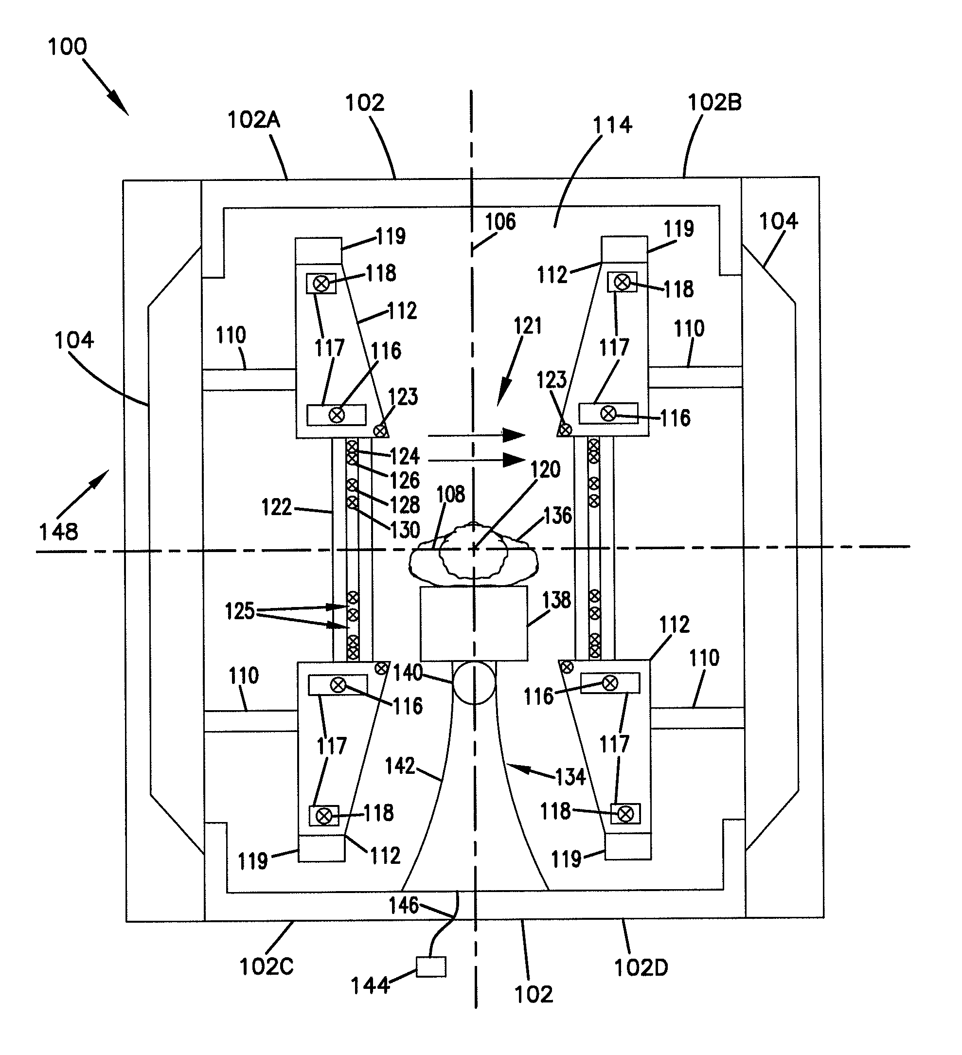
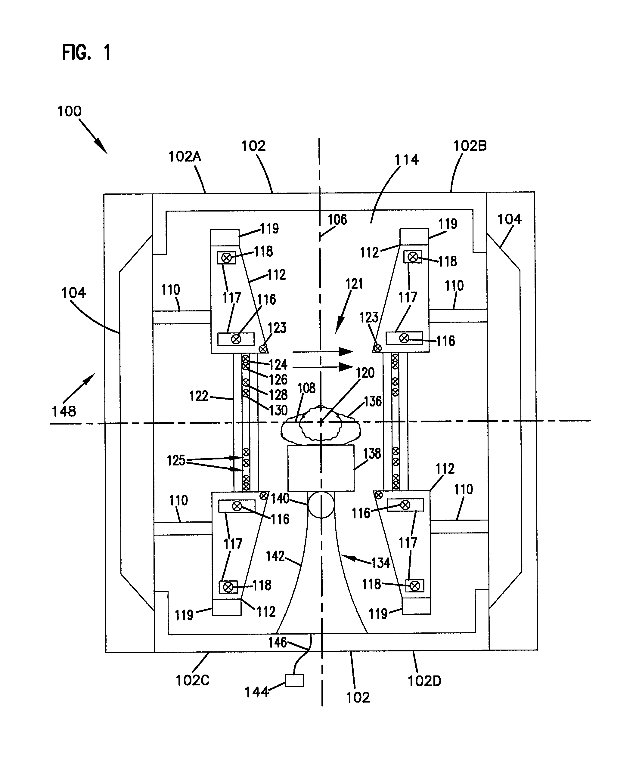
[0030]With reference to FIG. 1 of the Drawings, there is illustrated a first embodiment ...


PUM


Abstract

A magnetic resonance imaging configuration to straighten and otherwise homogenize the field lines in the imaging portion, creating improved image quality. Through use of calibrated corrective coils, magnetic field lines can be manipulated to improve uniformity and image quality. Additionally, when the apparatus is composed of non-ferromagnetic materials, field strengths can be increased to overcome limitations of Iron-based systems such as by use of superconductivity. A patient positioning apparatus allowing multi-positioning is also disclosed.

Description

TECHNICAL FIELD[0001]The present invention relates to magnets for magnetic resonance imaging apparatus, and to magnetic resonance imaging apparatus and methodologies incorporating those magnets.BACKGROUND OF THE INVENTION[0002]Magnetic Resonance Imaging (MRI) is a medical imaging technique commonly used in radiology to visualize internal body structures and functions, offering extraordinary tissue discrimination. Since its inception from the pioneering research efforts of Dr. Raymond Damadian, the advantages of MRI over other imaging techniques, e.g., computed tomography (CT), also known as Computerized Axial Tomography or CAT scanning and based on X-ray radiography, are many. For example, MRI provides much greater tissue contrasts and employs no ionizing radiation. These and numerous other advantages have made MRI the imaging tool of choice in medical diagnoses and treatment regimens.[0003]In magnetic resonance imaging, the body of a subject is positioned in a primary field magnet ...

Claims


Application Information

Patent Timeline
IPC IPC(8): G01V3/00
CPCG01R33/3806G01R33/3875G01R33/3815G01R33/3802G01R33/421G01R33/3873G01R33/307G01R33/3804G01R35/005G01R33/387G01R33/58H01F6/04H01F6/06
Inventor DAMADIAN, RAYMOND V.DANBY, GORDON T.HSIEH, HANKJACKSON, JOHN W.GELBIEN, MARKWAHL, WILLIAM H.GREEN, CHARLES A.
Owner FONAR
Learn More