Method and apparatus to increase ionization efficiency in an ion source

Active Publication Date: 2005-11-17
SCI & ENG SERVICES
View PDF5 Cites 8 Cited by
  • Summary
  • Abstract
  • Description
  • Claims
  • Application Information

AI Technical Summary

Benefits of technology

[0016] A further object of the present invention is to increase the electric field strength about areas around the sampling orifice to facilitate ion collection from large ionization areas and improve off-axis ionizati

Problems solved by technology

One potential drawback with the sampling interface designs discussed above is that the electric field may not be optimized at the location of irradiation (i.e. the l

Method used


Image

  • Method and apparatus to increase ionization efficiency in an ion source
  • Method and apparatus to increase ionization efficiency in an ion source
  • Method and apparatus to increase ionization efficiency in an ion source

Examples


Example

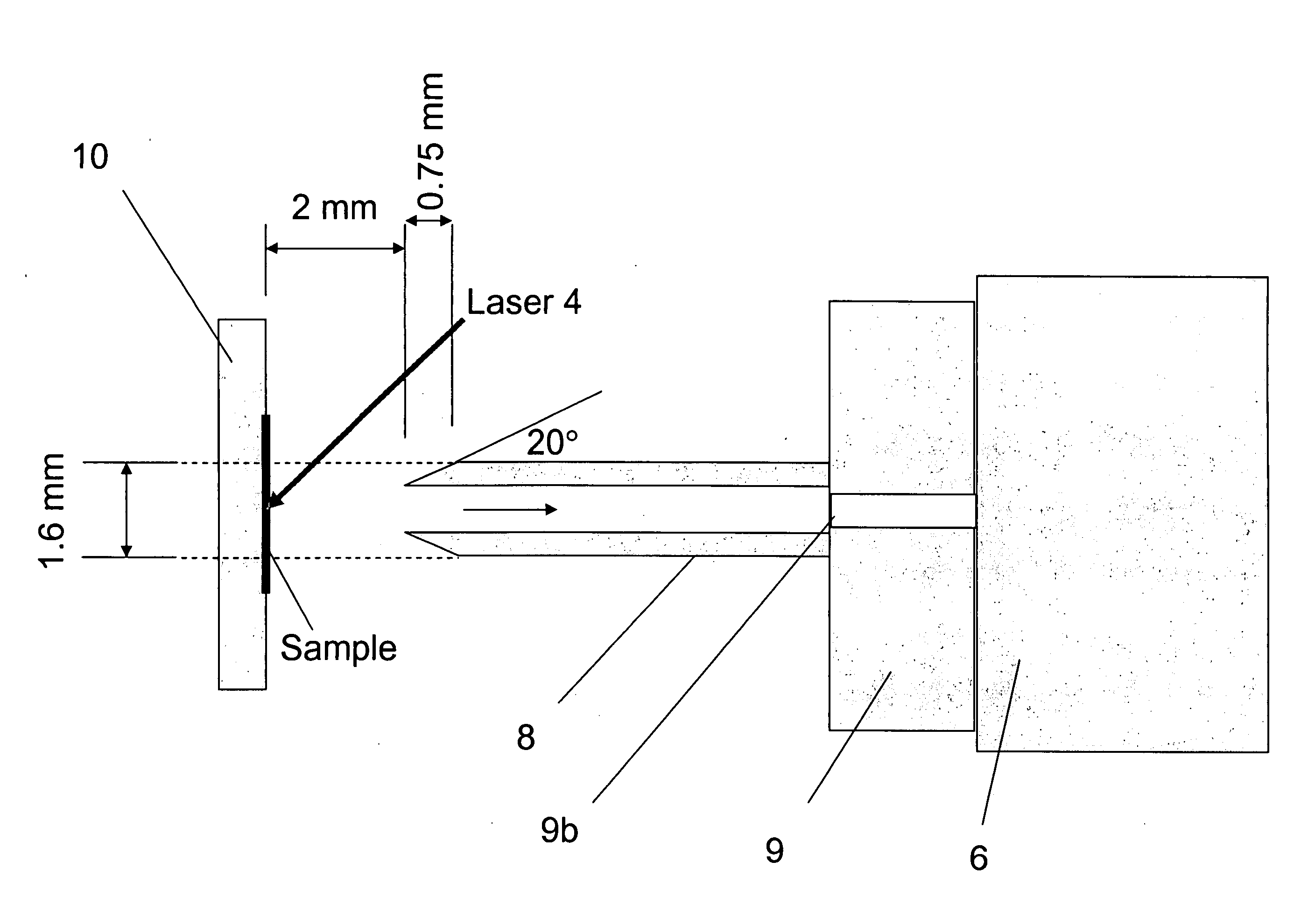
[0047] Referring now to the drawings, wherein like reference numerals designate identical, or corresponding parts throughout the several views, and more particularly to FIG. 6, FIG. 6 depicts one embodiment of the present invention as applied to an AP-MALDI ion source. Instead of a tapered capillary as shown in FIG. 1, FIG. 6 depicts an ion collection device in one embodiment of the present invention including an ion transfer device (e.g., extended capillary 8) and an end member (e.g., disk 18), in which the end member forms a sampling surface 16 extending parallel to the sample target plate 10. As shown, in this embodiment, the ion transfer device extends a distance from the mass spectrometer inlet flange 9. The extension distance is preferably a distance of at least 10 times an inner diameter of a sampling orifice 9b of the mass spectrometer 6. Details of extended capillary lengths suitable for various embodiment of the present invention are described in the above noted U.S. Seria...


PUM


Abstract

A method and an apparatus for collecting ions in which ions are produced from a sample in an ion source. An electric field is provided that is more uniform in an area adjacent the sample than in an area adjacent an inlet to the ion transfer device or that is larger in field strength at the sample than at a point removed from the sample towards the inlet of the ion transfer device. Ions are received into the electric field and transferred through the ion transfer device to a sampling orifice of the mass spectrometer. The apparatus includes an ion transfer device coupled to a sampling orifice of a mass spectrometer. The ion transfer device has an inlet with a surface that extends in a direction from an axis of the ion transfer device. The ion transfer device can extend a distance of at least 10 times an inner diameter of a sampling orifice of the mass spectrometer.

Description

CROSS-REFERENCE TO RELATED DOCUMENTS [0001] This application is related to U.S. Serial application Ser. No. 10 / 367,917 entitled “Method and Apparatus for Efficient Transfer of Ions into a Mass Spectrometer,” filed on Feb. 19, 2003, the entire contents of which is incorporated herein by reference. This application is related to U.S. Serial application Ser. No. 09 / 795,108 entitled “Capillary ion delivery device and method for mass spectroscopy,” filed on Mar. 1, 2001, the entire contents of which is incorporated herein by reference. This application is related to U.S. Pat. No. 5,965,884 entitled “Atmospheric Pressure Matrix-Assisted Laser Desorption,” issued Oct. 12, 1999, the entire contents of which is incorporated herein by reference.DISCUSSION OF THE BACKGROUND [0002] 1. Field of the Invention [0003] This invention relates in general to ion sources, and in particular to MALDI mass spectrometry ion sources especially with pulsed dynamic focusing. [0004] 2. Background of the Inventi...

Claims


Application Information

Patent Timeline
IPC IPC(8): H01J49/00H01J49/16H01J49/40
CPCH01J49/164H01J49/0404
Inventor TAN, PHILLIP V.LAIKO, VICTOR V.BERKOUT, VADYMDOROSHENKO, VLADIMIR M.
Owner SCI & ENG SERVICES
Why Eureka
Try Eureka