
Microwave reactor system enclosing a self-igniting plasma

Pending Publication Date: 2021-02-25
LYTEN INC
View PDF0 Cites 2 Cited by
  • Summary
  • Abstract
  • Description
  • Claims
  • Application Information

AI Technical Summary

Benefits of technology

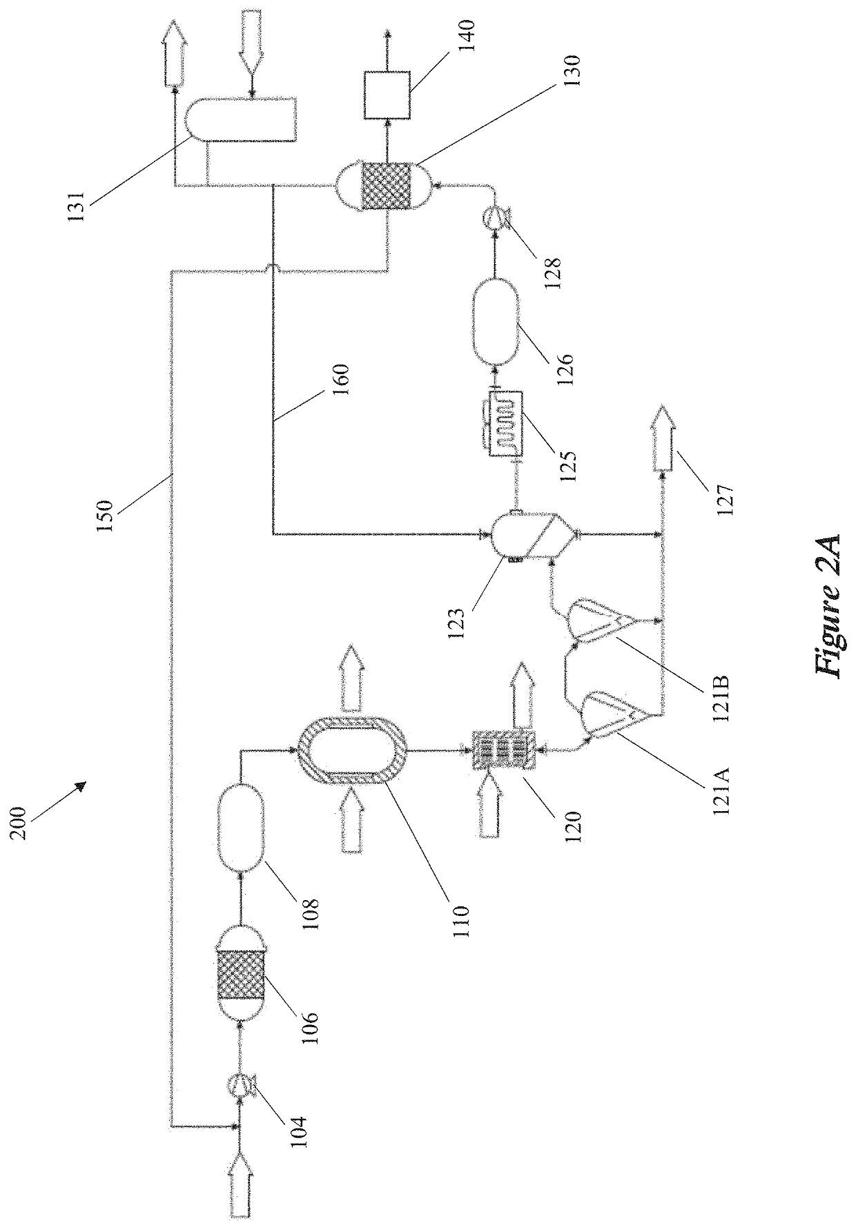
The patent describes a system for generating carbon-inclusive particles using a microwave energy source and a field-enhancing waveguide (FEWG). The system includes an expansion chamber and a constricted region where the plasma and the raw material are combined. The FEWG is designed to enhance the plasma and generate a high-density plasma. The system can also include a controller to adjust the electron density, electron temperature, or gas temperature in the FEWG. The carbon-inclusive particles produced by the system have several advantages, such as being graphene platelets fused together at substantially orthogonal angles. The system can also include a pair of electrodes to generate an electric field and facilitate the combination of the plasma and the raw material. The raw material can be converted into carbon-inclusive particles in the expansion chamber, which can have various shapes and be separated from the expansion chamber surfaces. Overall, the system can efficiently generate carbon-inclusive particles with improved properties.

Problems solved by technology

However, filtering carbon-containing particles from input hydrocarbon gases can present operational challenges.

Method used


Image

  • Microwave reactor system enclosing a self-igniting plasma
  • Microwave reactor system enclosing a self-igniting plasma
  • Microwave reactor system enclosing a self-igniting plasma

Examples


example 1

Chemical Processing System Gas-Solid Separation System

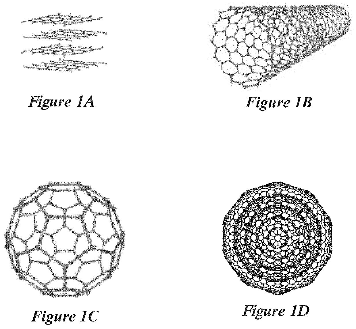
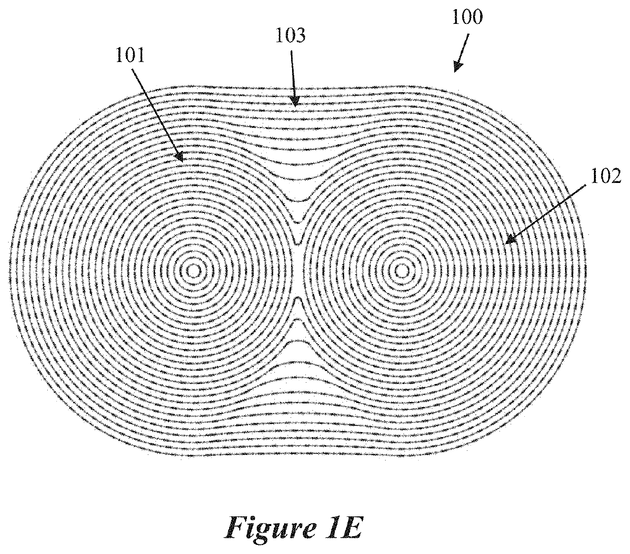
[0186]In this first example, carbon particles and aggregates containing graphite and graphene were generated using a microwave plasma reactor system, described in implementations above. The microwave plasma reactor in this example had a main body made from stainless steel with a quartz inner wall material. However, the quartz inner wall material is not needed in all cases, and similar carbon materials can be produced in reactors not containing quartz in or adjacent to the reaction zone. The reaction zone volume was approximately 45 cm3. The precursor material was methane and was optionally mixed with a supply gas (such as argon). The flow rate of methane was from 1 to 100 L / min, and the flow rate of the supply gas was from 0 to 100 L / min. With those flow rates and the tool geometry, the residence time of the gas in the reaction chamber was from approximately 0.001 second to approximately 2.0 seconds, and the carbon particle produ...

example 2

Chemical Processing System Gas-Solid Separation System

[0197]In this second example, carbon particles and aggregates containing graphite, graphene and amorphous carbon were generated using a microwave plasma reactor system as described in Example 1. The precursor material contained methane, or isopropyl alcohol (IPA), or ethanol, or a condensed hydrocarbon (such as hexane). The carbon-containing precursors were optionally mixed with a supply gas (such as argon). When gaseous methane was used, the flow rate of methane was from 1 to 100 L / min, and the flow rate of the supply gas was from 0 to 100 L / min. When the precursor material was a liquid mixture of IPA and ethanol, the flow rate of the liquid mixture was from 0.1 to 100 mL / min. In some other cases, a condensed hydrocarbon was used, and the flow rate of the hydrocarbon was approximately 3 L / min. With those flow rates and the tool geometry, the residence time of the gas in the reaction chamber was from approximately 0.001 second to...


PUM

PropertyMeasurementUnit
Temperatureaaaaaaaaaa
Lengthaaaaaaaaaa
Angleaaaaaaaaaa

Abstract

This disclosure provides a reactor system that includes a microwave energy source that generates a microwave energy, a field-enhancing waveguide (FEWG) coupled to the microwave source. The FEWG includes a field-enhancing zone having a cross-sectional area that decreases along a length of the FEWG. The field-enhancing zone includes a supply gas inlet that receives a supply gas, a reaction zone that generates a plasma in response to excitation of the supply gas by the microwave energy, a process inlet that injects a raw material into the reaction zone, and a constricted region that retains a portion of the plasma and combines the plasma and the raw material in response to the microwave energy within the reaction zone. An expansion chamber is in fluid communication with the constricted region facilitates expansion of the plasma. An outlet outputs a plurality of carbon-inclusive particles derived from the expanded plasma and the raw material.

Description

CROSS-REFERENCE TO RELATED APPLICATIONS[0001]This application is a continuation-in-part of U.S. patent application Ser. No. 16 / 283,234 entitled “Microwave Reactor System with gas-solids separation” and filed on Feb. 22, 2019, which is a continuation of U.S. patent application Ser. No. 15 / 725,928 entitled “Microwave Reactor System with gas-solids separation” and filed on Oct. 5, 2017, which claims priority to U.S. Provisional Patent Application No. 62 / 404,851 entitled “Microwave Reactor System” filed on Oct. 6, 2016 and to U.S. Provisional Patent Application No. 62 / 406,745 entitled “Bio-Gas System” filed on Oct. 11, 2016, all of which are assigned to the assignee hereof. The disclosures of all prior applications are considered part of and are incorporated by reference in this patent application in their respective entireties.TECHNICAL FIELD[0002]This disclosure relates generally to reactors for producing carbon agglomerates, and, more particularly, to reactors featuring multiple ener...

Claims


Application Information

Patent Timeline
IPC IPC(8): C01B32/05B01J8/00H01J37/32B01J19/12
CPCC01B32/05B01J8/0055H01J37/32192H01J37/32229B01D46/00C01P2004/61B01J2219/0886B01J2219/0894B01J2219/1296B01J19/126B01J2219/00022B01J2219/1209B01J2219/1248B01J2219/1269C01B32/154C01B32/16C01B32/184C01B32/205B01D45/12B01J19/088B01D46/71
Inventor TANNER, DAVIDCOOK, DANIELANZELMO, BRYCE H.KALLURI, RANJEETHSTOWELL, MICHAEL W.
Owner LYTEN INC
Learn More