
Supporting rod for tree supporting device

A support device and support rod technology, which is applied in application, cultivation, agriculture, etc., can solve the problems of reducing the firmness of the support, the connection method is thin, the iron wire binding strength is insufficient, etc., and achieve the effect of improving versatility

Inactive Publication Date: 2016-10-12
张维锋
View PDF7 Cites 1 Cited by
  • Summary
  • Abstract
  • Description
  • Claims
  • Application Information

AI Technical Summary

Problems solved by technology

2. In terms of function, occupying activity space
Especially for street trees or square shade trees, the messy support rods greatly occupy the space for pedestrians and activities, which has seriously affected the use function of the place
3. From the perspective of supporting effect, the firmness is not enough
First of all, whether it is a tension type or a support type, when a tree is subjected to lateral wind pressure, only the support members in one direction are under force, and the comprehensive effect of support has not been exerted.
Secondly, the way the support rods are connected to the tree and the way they are fixed to the ground are too thin to meet the force requirements of the support
In addition, the damage and decay of the support rods, as well as the insufficient strength and damage of the iron wire binding, can make the support system lose its function in a short period of time.
The support rod itself, the connection method between the support rod and the tree, and the fixing method between the support rod and the ground have not been analyzed systematically, which greatly affects the overall firmness of the support.
4. In terms of cost, it is not economical enough
However, those ground support poles that look relatively regular in shape have not fundamentally solved the above-mentioned several major drawbacks, and even significantly reduced the firmness of the support

Method used


Image

  • Supporting rod for tree supporting device
  • Supporting rod for tree supporting device
  • Supporting rod for tree supporting device

Examples


Embodiment Construction

[0033] The following description serves to disclose the present invention to enable those skilled in the art to carry out the present invention. The preferred embodiments described below are only examples, and those skilled in the art can devise other obvious variations. The basic principles of the present invention defined in the following description can be applied to other embodiments, variations, improvements, equivalents and other technical solutions without departing from the spirit and scope of the present invention.

[0034] Such as Figure 10 As shown, the support rod 10 for the tree support device of the invention cooperates with a hoop 20 to form a tree support device, so that after the trees are transplanted from the centralized planting site to the new planting environment, the tree support device can support the tree Keep trees in optimum planting condition without tipping or tipping over. In other words, the tree support device includes a hoop 20 and a plurali...


PUM


Abstract

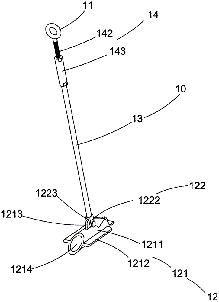
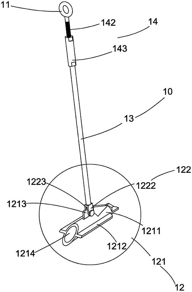
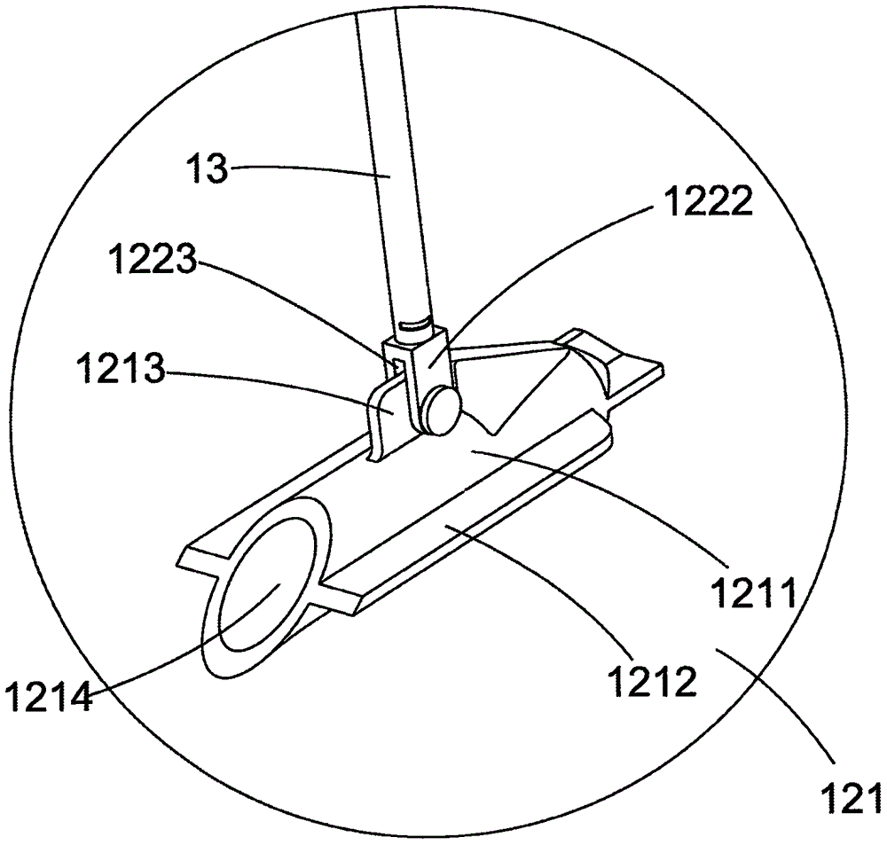
The invention discloses a supporting rod for a tree supporting device. The supporting rod comprises a connecting piece, a connecting rod, a ground anchor and an adjusting mechanism, wherein the ground anchor is adjustably arranged at the lower end part of the connecting rod; the adjusting mechanism comprises a first adjusting element which is arranged at the upper end part of the connecting rod, a second adjusting element which is arranged on the connecting piece and an adjusting body; the adjusting body is provided with an adjusting passage which is communicated with two end parts of the adjusting body; the first adjusting element and the second adjusting element are respectively and adjustably arranged at the lower end part and the upper end part of the adjusting passage of the adjusting body.

Description

technical field [0001] The invention relates to a garden tool, in particular to a support pole for a tree support device. Background technique [0002] In garden construction, tree transplantation is a very common and important work. Since newly planted trees cannot quickly take root deep into the soil in the short term to achieve stability through their own root fixation, almost all newly planted trees must be effectively braced to keep the tree from toppling over. [0003] Traditional tree support rods are generally made of bamboo poles, fir, steel pipes and other materials. The number of support rods will basically be about 1-4 according to the factors of tree diameter at breast height, crown width and height, which are usually so-called single-arm support, Pole support, triangular support, four-corner support, etc., are mostly connected with iron wires. The pole support mainly supports small trees, and the support height is generally about 60-100 cm; the single-arm sup...

Claims


Application Information

Patent Timeline
IPC IPC(8): A01G17/14
CPCA01G17/14
Inventor 张维锋
Owner 张维锋
Learn More