High-temperature heat shield assembly

Active Publication Date: 2018-06-14
TEXAS A&M UNIVERSITY
View PDF6 Cites 4 Cited by
  • Summary
  • Abstract
  • Description
  • Claims
  • Application Information

AI Technical Summary

Benefits of technology

[0003]A hermetic heat shield bladder is used to decrease a temperature at a wall of a vessel, such as a pipe or tank, that contains a high-temperatur

Problems solved by technology

For many of the applications, the performance and energy efficiency of the process improves with temperature up to 800° C. For such applications, the metals ordinarily used in vessels and piping cannot reliably operate in contact with molten salt at temperatures above 600° C. Such applications are typically limited by the strength of metals and al

Method used


Image

  • High-temperature heat shield assembly
  • High-temperature heat shield assembly
  • High-temperature heat shield assembly

Examples


Embodiment Construction

[0021]Embodiment(s) of the invention will now be described more fully with reference to the accompanying Drawings. The invention may, however, be embodied in many different forms and should not be construed as limited to the embodiment(s) set forth herein. The invention should only be considered limited by the claims as they now exist and the equivalents thereof.

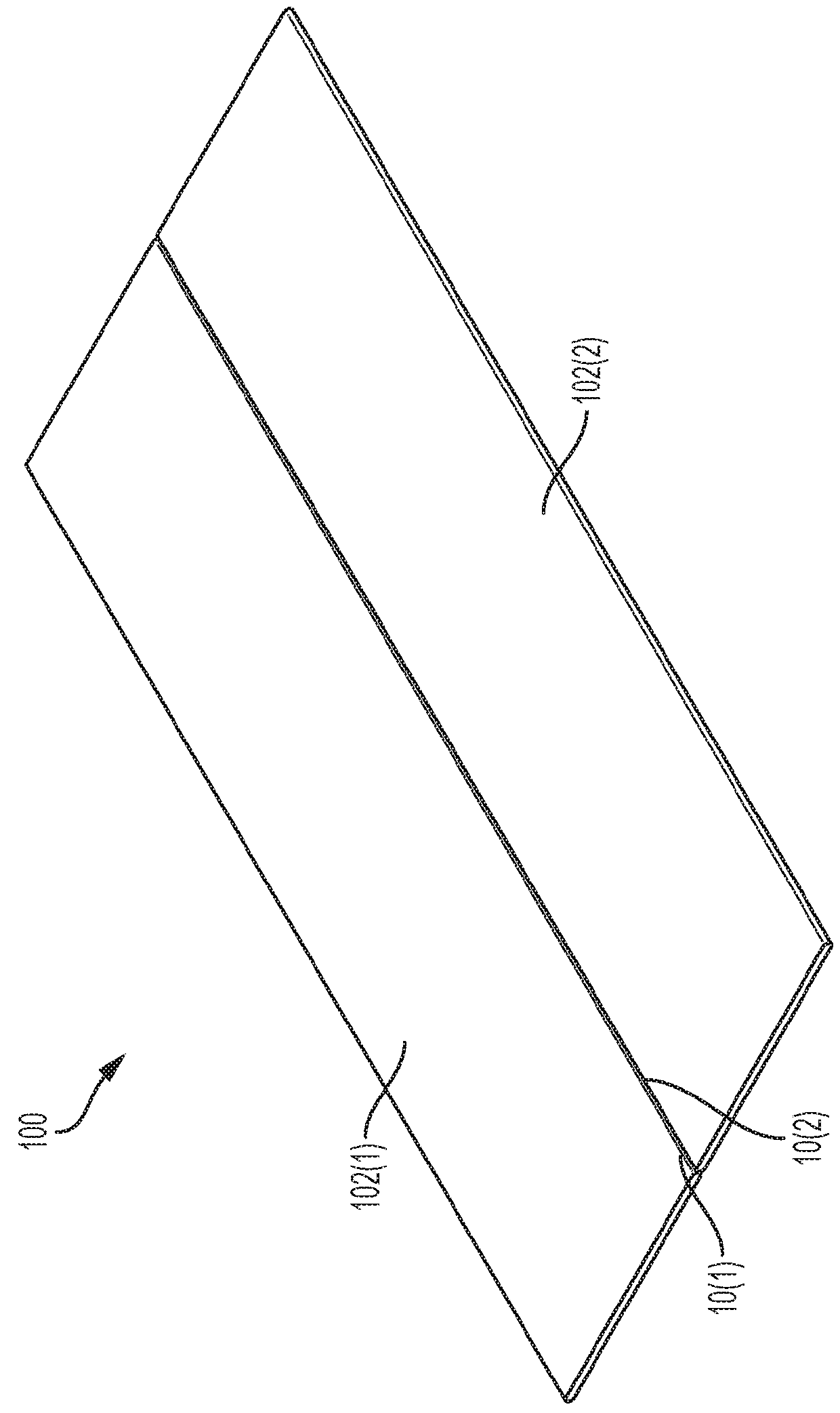
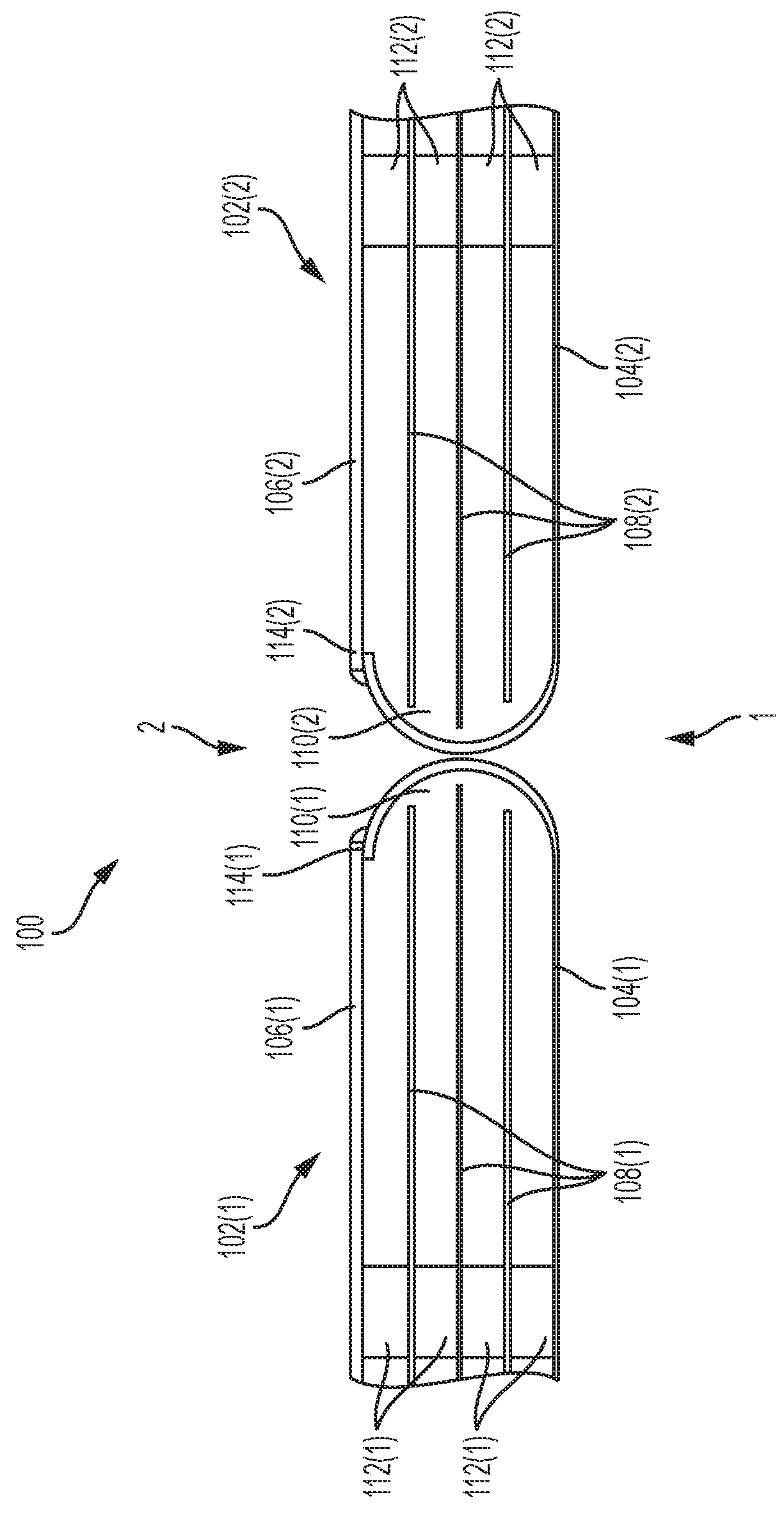
[0022]FIG. 1A is an isometric view of a hermetic heat shield bladder system 100 and FIG. 1B is a partial cross-sectional view of the hermetic heat shield bladder system 100. The bladder system 100 of FIGS. 1A and 1B includes a first hermetic heat shield bladder 102(1) and a second hermetic heat shield bladder 102(2). The first hermetic heat shield bladder 102(1) and the second hermetic heat shield bladder 102(2) comprise similar components and construction. The description of the first hermetic heat shield bladder 102(1) below is applicable to the second hermetic heat shield bladder 102(2) as well. FIG. 1A illustrates the fi...


PUM


Abstract

A heat shield bladder includes first and second sheets of insulating material that form a bladder between the first and second sheets. At least one reflective foil is disposed within the bladder and a plurality of spacers are disposed within the bladder and positioned to space the at least one reflective foil from the first and second sheets of insulating material. Multiple reflective foils may be disposed within the bladder with spacers between each reflective foil. The heat shield bladder may be rolled into a tube shaped and used inside a pipe or formed into panels that may be used to line a vessel.

Description

CROSS-REFERENCES TO RELATED APPLICATIONS[0001]This application claims the benefit under 35 U.S.C. § 119(e) of U.S. Provisional Patent Application No. 62 / 433,082, filed Dec. 12, 2016, which is incorporated herein by reference in its entirety as if fully set forth herein.BACKGROUND OF THE INVENTION[0002]The present disclosure relates to the field of heat transfer, and more particularly to the provision of thermal isolation between a volume of high-temperature fluid and a vessel that contains the high-temperature fluid. There are applications that require use of a high-temperature fluid to store heat and to deliver the heat for use in an application, such as electric power generation, control of a chemical synthesis reaction, extraction of ore, high-efficiency electric batteries, secondary recovery of oil in a producing stratum, or heat transfer and neutronics in a critical or subcritical fission core. In some of the applications, the high-temperature fluid with most beneficial propert...

Claims


Application Information

Patent Timeline
IPC IPC(8): B01J19/00
CPCF24S80/60B01J19/0013B01J2219/00155B01J19/18B01J2219/0009B01J2219/0015Y10T428/234Y10T428/231Y02E10/40F24S60/00F16L59/147B32B3/00F16L59/02
Inventor MCINTYRE, PETER
Owner TEXAS A&M UNIVERSITY
Why Eureka
Try Eureka