Vehicle control device

Active Publication Date: 2018-07-26
TOYOTA JIDOSHA KK
View PDF0 Cites 4 Cited by
  • Summary
  • Abstract
  • Description
  • Claims
  • Application Information

AI Technical Summary

Benefits of technology

[0019]With the above configuration, this vehicle control device can cause the vehicle to arrive on the potential route at the reference arrival position if the road on which the vehicle is traveling is a freeway and can cause the vehicle to arrive on the potential route at a position that is nearer t

Problems solved by technology

However, when the target time (or the target distance) is constant, there is a possibility that a route not following the shape of the road is generated or that a route with low reliability is generated.
Furthermore, as the road environment around the vehicle becomes more complic

Method used


Image

  • Vehicle control device
  • Vehicle control device
  • Vehicle control device

Examples


first embodiment

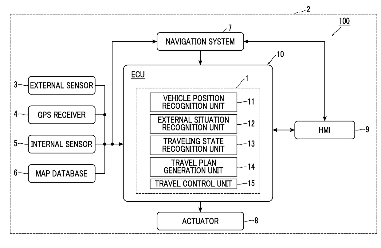
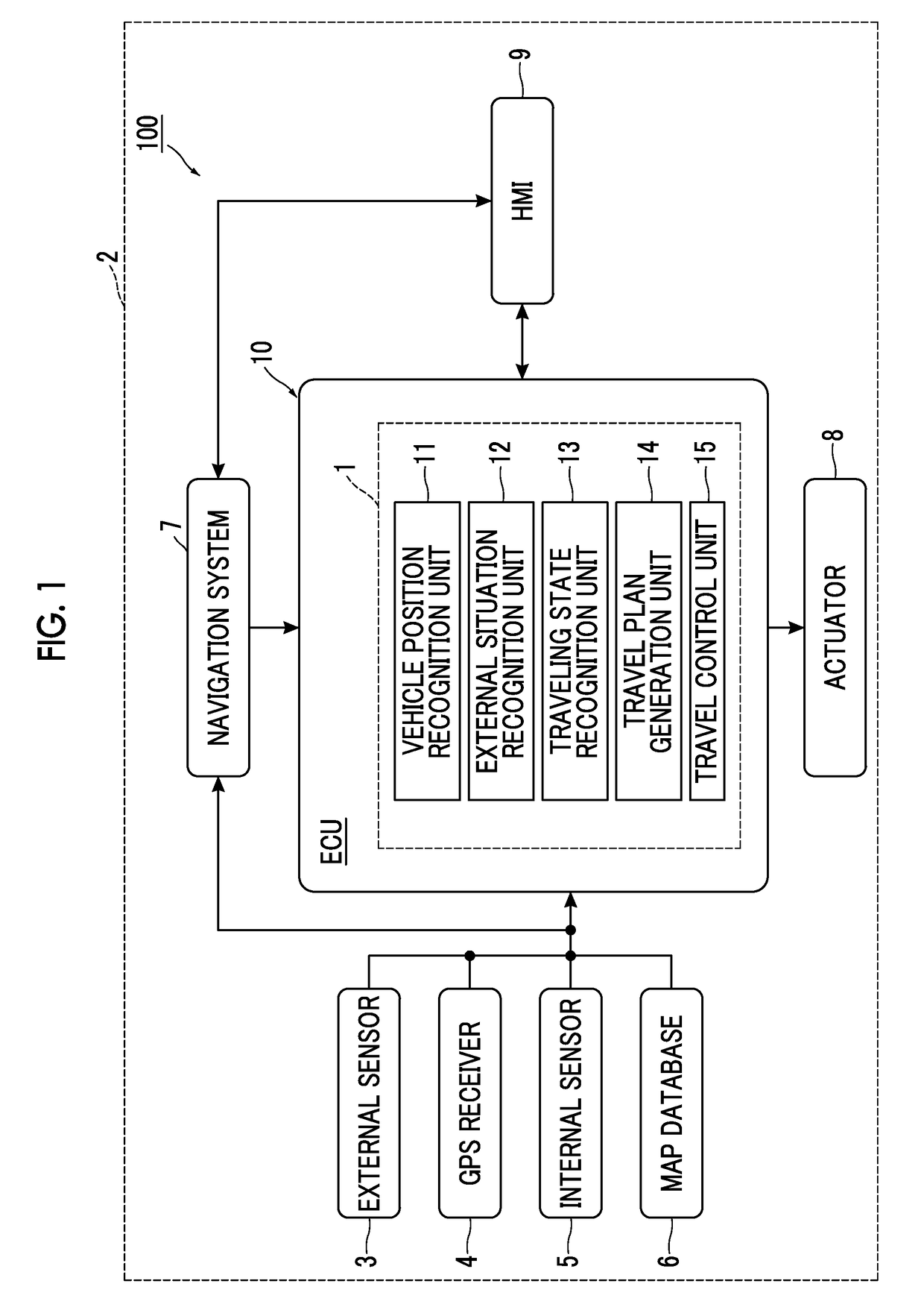
[0040]FIG. 1 is a block diagram showing a configuration of a vehicle 2 that includes a vehicle control device 1 according to a first embodiment. As shown in FIG. 1, a vehicle system 100 is mounted on the vehicle 2 such as a passenger car. The vehicle system 100 is a system that causes the vehicle 2 to travel in the autonomous driving mode. Autonomous driving is a vehicle control operation for autonomously driving the vehicle 2 toward a preset destination with no need for a driver to perform the driving operation. As will be described later, the vehicle system 100 includes the vehicle control device 1 that controls the traveling of the vehicle 2 based on a target route.

[0041]The vehicle system 100 includes an external sensor 3, a Global Positioning System (GPS) receiver 4, an internal sensor 5, a map database 6, a navigation system 7, an actuator 8, a Human Machine Interface (HMI) 9, and an Electronic Control Unit (ECU) 10.

[0042]The external sensor 3 is a detector that detects the si...

second embodiment

[0103]A vehicle control device according to a second embodiment differs from the vehicle control device 1 according to the first embodiment in that the information used for determining whether the reference arrival position is used as the target arrival position is different. The other part of the second embodiment is the same as that of the first embodiment. Therefore, the description of the configuration and the operation similar to those of the vehicle control device 1 will not be repeated.

[0104]The arrival position determination unit of the vehicle control device according to the second embodiment determines, as the target arrival position, a position where the vehicle 2 will arrive on the potential route in a time shorter than the target time or over a distance shorter than the target distance, according to the external situation at the reference arrival position. That is, the target arrival position is determined using, not the map information (road curvature) of the reference...

third embodiment

[0114]A vehicle control device according to a third embodiment differs from the vehicle control device 1 according to the first embodiment in that the information used for determining whether the reference arrival position is used as the target arrival position is different. The other part of the third embodiment is the same as that of the first embodiment. Therefore, the description of the configuration and the operation similar to those of the vehicle control device 1 will not be repeated.

[0115]The arrival position determination unit of the vehicle control device according to the third embodiment determines, as the target arrival position, a position where the vehicle 2 will arrive on the potential route in a time shorter than the target time or over a distance shorter than the target distance, according to the map information (road type). That is, the target arrival position is determined using, not the road curvature at the reference arrival position, but the road type. The road...


PUM


Abstract

A vehicle control device includes a map database and at least one electronic control unit. The electronic control unit is configured to calculate a reference arrival position based on a target time or a target distance. The at least one electronic control unit is configured to determine, according to the map information or the external situation at the reference arrival position, as a target arrival position, a position where the vehicle arrives on the potential route in a time different from the target time or over a distance different from the target distance. The at least one electronic control unit is configured to calculate a transition route from the road position to the target arrival position, and generate the target route by connecting the transition route and the potential route following the target arrival position.

Description

INCORPORATION BY REFERENCE[0001]The disclosure of Japanese Patent Application No. 2017-010529 filed on Jan. 24, 2017 including the specification, drawings and abstract is incorporated herein by reference in its entirety.BACKGROUND1. Technical Field[0002]The present disclosure relates to a vehicle control device.2. Description of Related Art[0003]US 2015 / 0197246 A discloses a device for generating a route along which a vehicle will travel. This device calculates, in advance, a plurality of potential routes along which a vehicle can travel within a lane, based on the map information such as lane boundaries. After that, based on the sensor information and so on, the device selects, from the plurality of calculated potential routes, a potential route by which the vehicle can keep its distance from an obstacle. Then, the device generates a target route along which the vehicle can transit smoothly from the current route to the selected potential route for continued traveling.SUMMARY[0004]...

Claims


Application Information

Patent Timeline
IPC IPC(8): G05D1/02G01C21/36
CPCG05D1/0274G01C21/36G05D2201/0213B60W30/10G05D1/0212B60W2556/45B60W2552/00B60W2556/50G01C21/34B60W30/18163B60W30/12B60W30/18145B60W2552/30B60W30/00
Inventor SATO, KUNIHITOICHIKAWA, KENTAROHIRANO, MAIKOOKUMURA, BUNYO
Owner TOYOTA JIDOSHA KK
Why Eureka
Try Eureka