Noise suppression apparatus, noise suppression method, and non-transitory recording medium

a noise suppression and noise technology, applied in the field of noise suppression apparatus, noise suppression method, non-transitory recording medium, can solve the problems of difficult detection of pulse noise and estimate the signal level of pulse noise, and the inability to predict when pulse noise occurs, so as to achieve the effect of properly suppressing pulse noise in the input signal

Active Publication Date: 2018-11-15
PANASONIC INTELLECTUAL PROPERTY CORP OF AMERICA
View PDF3 Cites 3 Cited by
  • Summary
  • Abstract
  • Description
  • Claims
  • Application Information

AI Technical Summary

Benefits of technology

[0007]According to the present disclosure, it is possible to properly suppress pulse noise in an input signal even in a situation in which the level of the input signal changes.

Problems solved by technology

Unlike stationary noise such as air conditioner blower noise, nonstationary noise such as pulse noise occurs unexpectedly and suddenly and thus it is difficult to predict when pulse noise occurs.
Therefore, it is difficult to detect pulse noise and estimate a signal level of the pulse noise.
For example, in a car radio receiver (a radio receiver installed in a vehicle), when degradation occurs in condition of a radio wave of a radio broadcasting being received, pulse noise may occur which may annoy listeners.
In a video conference system, an operation sound of a keyboard used to input data into a computer located near a microphone can result in pulse noise, and a reproduced voice / sound output from a speaker may be very annoying.

Method used


Image

  • Noise suppression apparatus, noise suppression method, and non-transitory recording medium
  • Noise suppression apparatus, noise suppression method, and non-transitory recording medium
  • Noise suppression apparatus, noise suppression method, and non-transitory recording medium

Examples


first embodiment

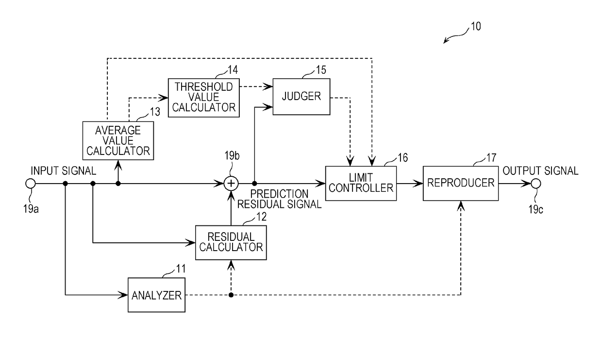
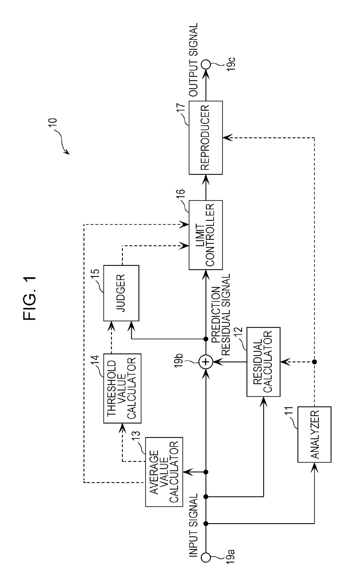
[0029]An embodiment is described below taking as an example a noise suppression apparatus 10. The noise suppression apparatus 10 is an apparatus that operates such that when a voice / sound signal including pulse noise is given as an input signal, an output signal is generated such that the pulse noise in the input signal is suppressed to a low level. The noise suppression apparatus 10 may be used as a stand along apparatus or may be embedded in, for example, a car radio receiver, a sound collector, an audio device, or the like.

[0030]FIG. 1 is a block diagram illustrating a configuration of the noise suppression apparatus 10. The noise suppression apparatus 10 includes, as shown in FIG. 1, an analyzer 11, a residual calculator 12, an average value calculator 13, a threshold value calculator 14, a judger 15, a limit controller 16, and a reproducer 17. To show a flow of a signal in the noise suppression apparatus 10, FIG. 1 also illustrates input / output nodes and the like such as an inp...


PUM


Abstract

A noise suppression apparatus disclosed is capable of suppressing pulse noise in an input signal even in a situation in which the level of the input signal changes. The pulse noise mixed in the input signal is suppressed, and linear prediction coefficients for the input signal is derived by linear prediction analysis. A prediction residual signal is then calculated from the input signal using the linear prediction coefficient. A threshold value is calculated based on the signal level of the input signal and the signal level of the prediction residual signal is compared with the threshold value. A limit control is performed on the prediction residual signal depending on a result of the comparison, and an output signal is generated based on the prediction residual signal having been subjected to the limit control using the linear prediction coefficient.

Description

BACKGROUND1. Technical Field[0001]The present disclosure relates to a noise suppression apparatus, a noise suppression method, and a non-transitory recording medium.2. Description of the Related Art[0002]Unlike stationary noise such as air conditioner blower noise, nonstationary noise such as pulse noise occurs unexpectedly and suddenly and thus it is difficult to predict when pulse noise occurs. Therefore, it is difficult to detect pulse noise and estimate a signal level of the pulse noise. For example, in a car radio receiver (a radio receiver installed in a vehicle), when degradation occurs in condition of a radio wave of a radio broadcasting being received, pulse noise may occur which may annoy listeners. In a video conference system, an operation sound of a keyboard used to input data into a computer located near a microphone can result in pulse noise, and a reproduced voice / sound output from a speaker may be very annoying.[0003]In a conventional technique, it is known to perfo...

Claims


Application Information

Patent Timeline
Patent Type & Authority Applications(United States)
IPC IPC(8): H03G3/34
CPCH03G3/345G10L21/0264G10L19/025G10L21/0208G10L25/12
Inventor YUZURIHA, SHINICHI
Owner PANASONIC INTELLECTUAL PROPERTY CORP OF AMERICA
Why Eureka
Try Eureka