Liquid crystal display drive circuit

A liquid crystal drive circuit and circuit technology, which can be used in instruments, static indicators, etc., to solve problems such as liquid crystal LC afterimages.

Inactive Publication Date: 2010-06-09
SANYO ELECTRIC CO LTD +1
View PDF2 Cites 0 Cited by
  • Summary
  • Abstract
  • Description
  • Claims
  • Application Information

AI Technical Summary

Problems solved by technology

This is because if a DC bias voltage is continuously applied to the liquid crystal LC for a long period of time, it will cause image sticking on the liquid crystal LC.

Method used


Image

  • Liquid crystal display drive circuit
  • Liquid crystal display drive circuit
  • Liquid crystal display drive circuit

Examples


Embodiment Construction

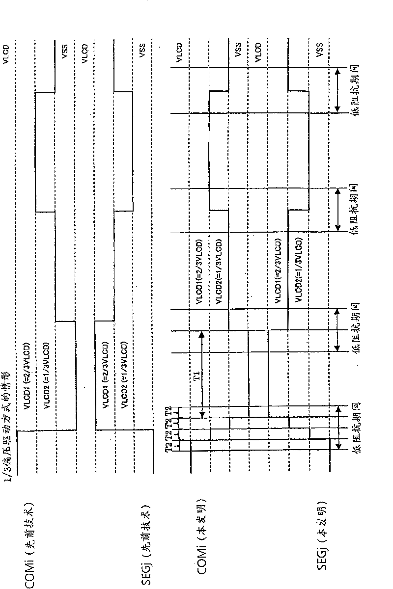
[0063] Before describing the embodiment of the present invention, firstly, the 1 / 3 bias driving method is taken as an example to examine the situation where the impulse noise of the liquid crystal panel 12 is likely to be generated. For example, imagine output as Figure 13 The common signal COM1, COM2, and the segment signal SEG1 to the liquid crystal panel 12 are shown. In this case, during the period TA, the common signal COM1 changes from a high potential VLCD to a low potential VSS (=ground potential 0V), and the segment signal SEG1 changes from a low potential VSS to a high potential VLCD in turn. Therefore, the potential difference between the corresponding electrodes reaches VLCD, and the segment SEG1 corresponding to the common COM1 is lit.

[0064] In this period TA, although the common signal COM2 changes from the second intermediate potential VLCD2 to VLCD1, since the segment signal SEG1 rises from the low potential VSS to the high potential VLCD at this time, impulse...


PUM


Abstract

A liquid crystal display drive circuit that suppresses a pulse noise in a liquid crystal display panel without increasing a mounting area is offered. A common signal COMi is varied in a staircase waveform with an increment of 1 / 3 VLCD in such a way that a high electric potential VLCD->a first intermediate electric potential VLCD1->a second intermediate electric potential VLCD2->a low electric potential VSS, when the common signal COMi varies by the maximum amplitude, in other words, when the common signal COMi makes a transition from the high electric potential VLCD to the low electric potential VSS. The segment signal SEGj is varied similarly in a staircase waveform in such a way that the low electric potential VSS->the second intermediate electric potential VLCD2->the first intermediate electric potential VLCD1->the high electric potential VLCD when the segment signal SEGj makes a transition from the low electric potential VSS to the high electric potential VLCD. A peak value of the pulse noise due to a capacitive coupling can be reduced to 1 / 3 of that in the prior art.

Description

[0001] 【Related application cases】 [0002] This application claims the rights of the invention patent 2008-274548 filed in Japan on October 24, 2008. Technical field [0003] The present invention relates to a liquid crystal driving circuit that outputs a segment signal and a common signal for turning on or off a liquid crystal display segment. Background technique [0004] Generally speaking, a segment type liquid crystal display panel performs display by applying a common signal and a segment signal to the common electrode and the segment electrode, respectively. The common signal is a signal that repeatedly exhibits a fixed waveform pattern. On the other hand, the segment signal is an arbitrary waveform corresponding to the display data. An electric field corresponding to the common signal and the segment signal is generated between the common electrode and the segment electrode, so that the liquid crystal disposed between the electrodes is turned on / off, thereby controlling t...

Claims


Application Information

Patent Timeline
Patent Type & Authority Applications(China)
IPC IPC(8): G09G3/36G09G3/20
CPCG09G2310/066G09G3/3696G09G2320/0209G09G3/3614G09G3/20G09G3/36
Inventor 后藤贤介德永哲也片桐典和
Owner SANYO ELECTRIC CO LTD
Why Eureka
Try Eureka