Unilateral driving mechanism for a portable infusion system

a driving mechanism and infusion system technology, applied in the field of medical appliances, can solve the problems low precision, etc., and achieve the effects of large volume, high power consumption, and high cos

Active Publication Date: 2019-04-25
MEDTRUM TECH
View PDF0 Cites 61 Cited by
  • Summary
  • Abstract
  • Description
  • Claims
  • Application Information

AI Technical Summary

Benefits of technology

[0005]Regarding the above-mentioned shortcomings of the prior art, the present invention provides a unilateral driving mechanism for a portable infusion system, to solve the problems including large volume, high power consumption, high cost, inconvenience in using and low precision in controlling administration of the driving mechanism in prior arts.

Problems solved by technology

Currently, drug infusion products majorly realize administration by combining motors and transmission mechanism, which has disadvantages as complex structure, large volume, high power consumption, low precision, high cost, difficult maintenance and inconvenience in using of the drug infusion product.
Moreover, the power output from motor operation usually needs to be converted into the driving force of the push rod to realize administration by a decelerator or a driving thread of an output shaft of a decelerator, during whose process a series of movements take place, so the functioning of the motor cannot always guarantee the normal operation of the push rod and the accuracy of the administration, which causes safety risks.
Furthermore, incidents of abnormal flow rate control of the products in the current market have been occurring from time to time.
Ultra high flow rate may cause an overdose and toxicity; and ultra low flow rate may result in doses too small to reach any therapeutic effect.
One of the most likely reasons for inaccurate control of the flow rate is the imperfect design of the monitoring system, and the products in the current market have not reached the level of accurate control of the flow rate.

Method used


Image

  • Unilateral driving mechanism for a portable infusion system
  • Unilateral driving mechanism for a portable infusion system

Examples


embodiment1

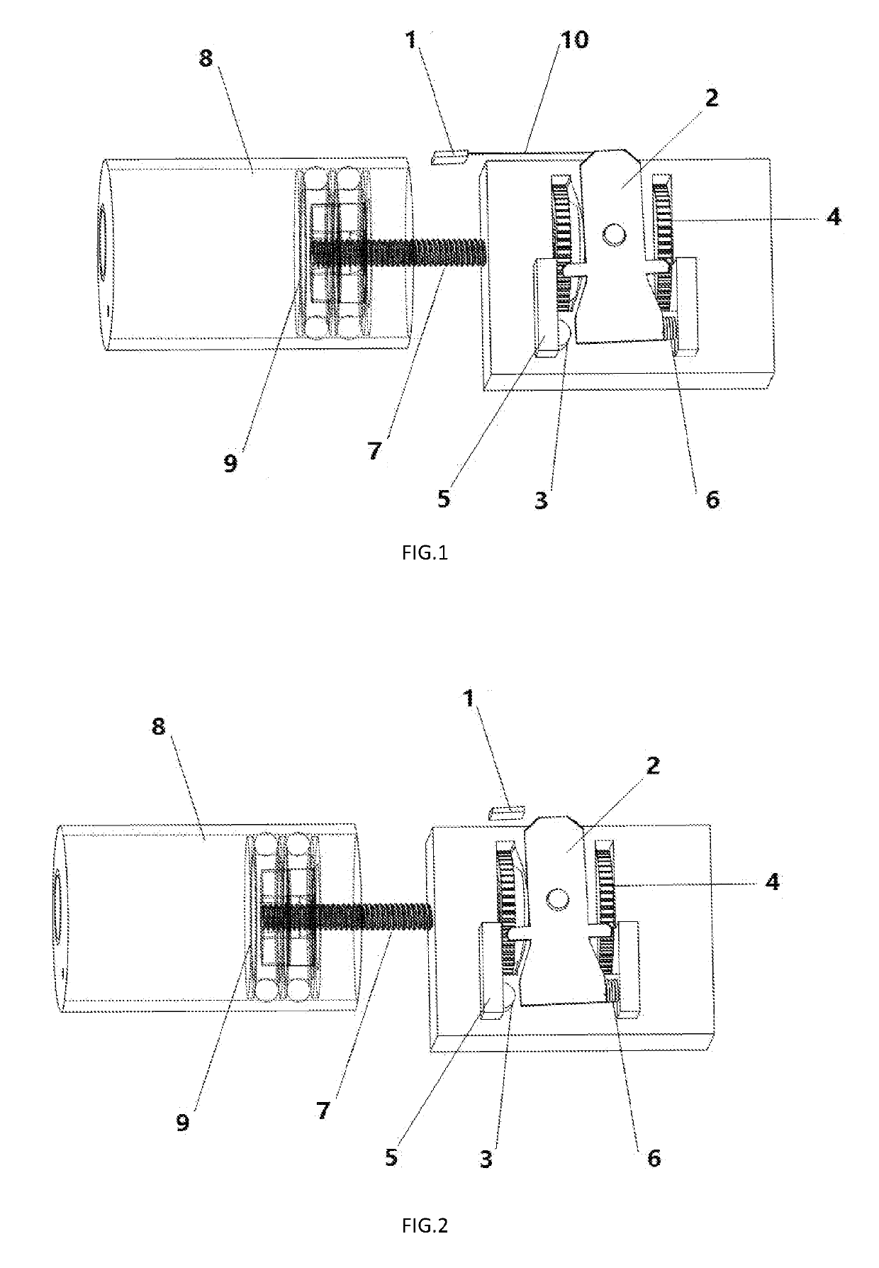
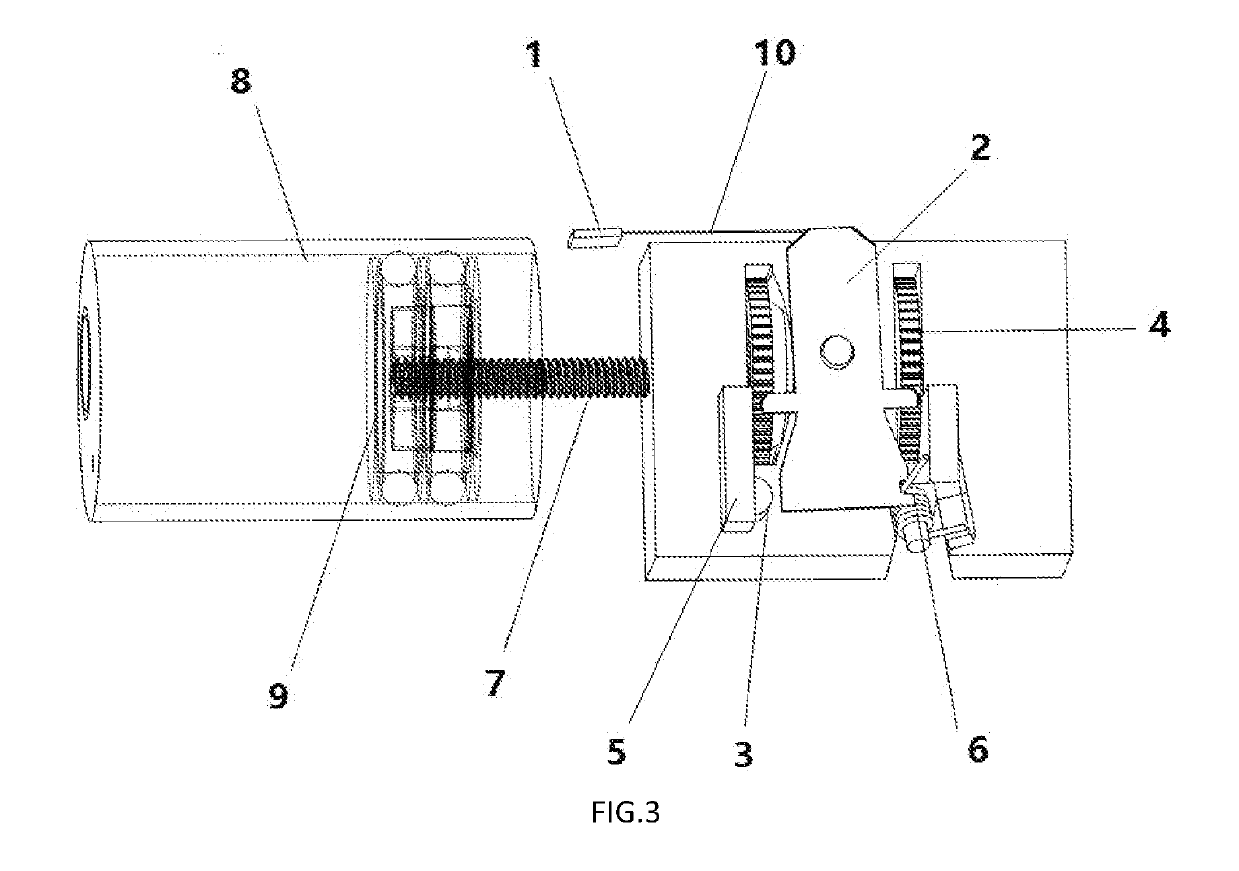
[0045]Referring to the FIG. 1, provided is an exemplary embodiment of a unilateral driving mechanism for a portable infusion system in the present invention, comprising:[0046]An actuator 1, a swinging part 2, gears 4, blockers 5, a tension spring 6, a rod 7, a reservoir 8, a plunger 9, and a wire 10;[0047]The actuator 1 is connected with the swinging part 2 by the wire 10, one end of the rod 7 is connected with the gears 4, the other end of the rod 7 is connected with the plunger 9, one lower limb of the swinging part 2 is connected with the tension spring 6; a monitoring element 3 configured to monitor the movement of the swinging part 2 and a control circuit are further set on the blocker 5;[0048]When there is no unilateral drive applied, the tension spring 6 is in its initial state, and the lower limb of the swinging part 2 which is not connected with the tension spring 6 is separated from the blocker 5;[0049]When there is a unilateral drive applied on the actuator 1, the head of...

embodiment2

[0052]Referring to the FIG. 2, also provided is an exemplary embodiment of a unilateral driving mechanism for a portable infusion system in the present invention, comprising:[0053]An actuator 1, a swinging part 2, gears 4, blockers 5, a compression spring 6, a rod 7, a reservoir 8, and a plunger 9;[0054]The actuator 1 is a piezoelectric actuator, one end of the rod 7 is connected with the gears 4, the other end of the rod 7 is connected with the plunger 9, one lower limb of the swinging part 2 is connected with the compression spring 6; a monitoring element 3 configured to monitor the movement of the swinging part 2 and a control circuit are further set on the blocker 5, and the monitoring element 3 is a metallic element;[0055]When there is no piezoelectric drive applied, the compression spring 6 is in its initial state, and the lower limb of the swinging part 2 which is not connected with the compression spring 6 contacts the blocker 5;[0056]When there is a piezoelectric drive appl...

embodiment3

[0059]Referring again to the FIG. 2, also provided is an exemplary embodiment of a unilateral driving mechanism for a portable infusion system in the present invention, comprising:[0060]An actuator 1, a swinging part 2, gears 4, blockers 5, a compression spring 6, a rod 7, a reservoir 8, and a plunger 9;[0061]The actuator 1 is a magnet actuator, one end of the rod 7 is connected with the gears 4, the other end of the rod 7 is connected with the plunger 9, one lower limb of the swinging part 2 is connected with the compression spring 6; a monitoring element 3 configured to monitor the movement of the swinging part 2 and a control circuit are further set on the blocker 5, and the monitoring element 3 is a metallic element;[0062]When there is no magnet drive applied, the compression spring 6 is in its initial state, and the lower limb of the swinging part 2 which is not connected with the compression spring 6 contacts the blocker 5;[0063]When there is a magnet drive applied on the magn...


PUM


Abstract

A unilateral driving mechanism for a portable infusion system is provided. The unilateral driving mechanism comprises an actuator (1), a swinging part (2), gears (4), blockers (5), a compression spring (6), a rod (7), a reservoir (8), a plunger (9) and a control circuit. One end of the rod (7) is connected with the gears (4), the other end of the rod (7) is connected with the plunger (9), and one lower limb of the swinging part (2) is connected with the spring (6). The unilateral driving mechanism for a portable infusion system has advantages of compact structure, small volume, low power consumption, low cost, high precision and convenience in use.

Description

TECHNICAL FIELD[0001]The present invention generally relates to the field of medical appliance, specifically to a unilateral driving mechanism for a portable infusion system.BACKGROUND OF THE INVENTION[0002]Currently, drug infusion products majorly realize administration by combining motors and transmission mechanism, which has disadvantages as complex structure, large volume, high power consumption, low precision, high cost, difficult maintenance and inconvenience in using of the drug infusion product. Moreover, the power output from motor operation usually needs to be converted into the driving force of the push rod to realize administration by a decelerator or a driving thread of an output shaft of a decelerator, during whose process a series of movements take place, so the functioning of the motor cannot always guarantee the normal operation of the push rod and the accuracy of the administration, which causes safety risks.[0003]Furthermore, incidents of abnormal flow rate contro...

Claims


Application Information

Patent Timeline
Patent Type & Authority Applications(United States)
IPC IPC(8): A61M5/142A61M5/145A61M5/168
CPCA61M5/14244A61M5/1452A61M5/16804A61M2005/14533A61M2005/14208A61M5/14A61M5/142A61M5/31576
Inventor YANG, CUIJUN
Owner MEDTRUM TECH
Why Eureka
Try Eureka