Light distribution system for freezer

a technology for distribution systems and freezers, applied in the field of lighting, can solve problems such as worse overall visual perception, and achieve the effects of strong focusing performance, enhanced focusing performance, and enhanced focusing performan

Active Publication Date: 2019-05-30
SELF ELECTRONICS CO LTD +3
View PDF0 Cites 6 Cited by
  • Summary
  • Abstract
  • Description
  • Claims
  • Application Information

AI Technical Summary

Benefits of technology

[0016]Compared with the prior art, the minimum curvature radius of the contour line on the first convex lens exit surface of the strip-shaped polarizing lens of the LED strip lamp of the present invention is larger than the maximum curvature radius of the contour line on the second convex lens exit surface. Therefore, the second convex lens exit surface has a stronger focusing performance than the first convex lens exit surface. Moreover, the radius of curvature of the first convex lens exit surface gradually decreases in the direction toward the optical axis to gradually enhance the focusing performance and the radius of curvature of the second convex lens exit surface gradually decreases in the direction away from the optical axis to gradually enhance the focusing performance. Therefore, the irradiance in the irradiated area where the irradiation distance is gradually transitioned from near to far can be uniform while the first convex lens exit surface irradiates vicinity and the second convex lens exit surface irradiates remote area. In addition, due to the arrangement of the transition surface of the strip-shaped polarizing lens and the arrangement of the reflecting surface on the lamp holder, light can be irradiated onto the sub-light region of the illuminated surface, as a result, the entire illuminated surface is illuminated and the light experience can be improved.

Problems solved by technology

Since the LED chip that is once packaged can distribute light in its range of light angles and cannot meet the lighting requirements in most cases, it is generally required to use a lens for secondary light distribution processing.
However, such a method of supplementing light still has a problem of uneven light distribution in the illumination of the near-illuminated and distantly irradiated transitional illumination areas, thereby making the overall visual perception worse.

Method used


Image

  • Light distribution system for freezer
  • Light distribution system for freezer
  • Light distribution system for freezer

Examples


Embodiment Construction

[0022]The present application is illustrated by way of the following detailed description based on of the accompanying drawings. It should be noted that illustration to the embodiment in this application is not intended to limit the invention.

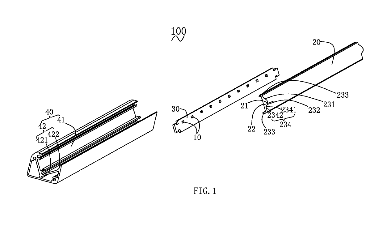
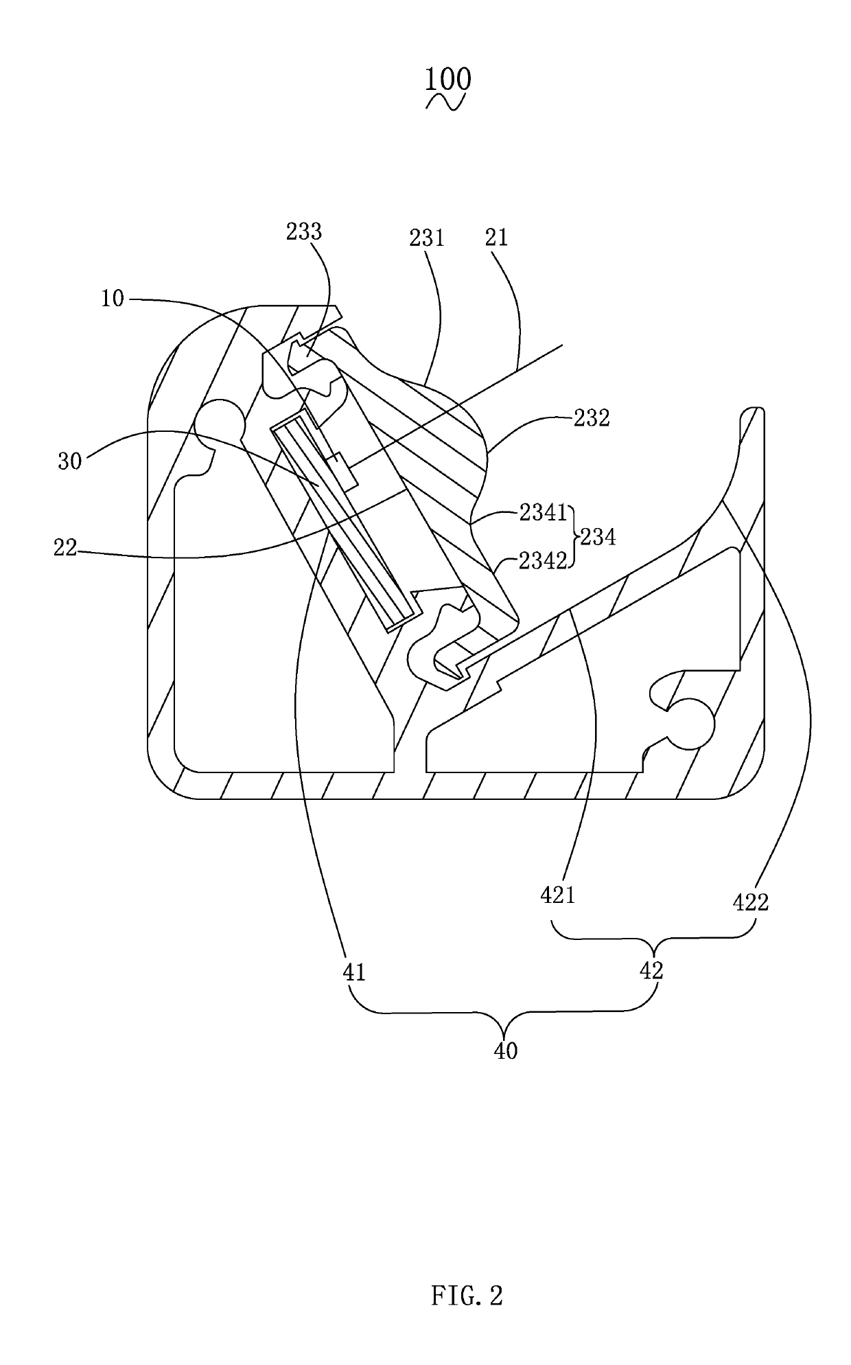
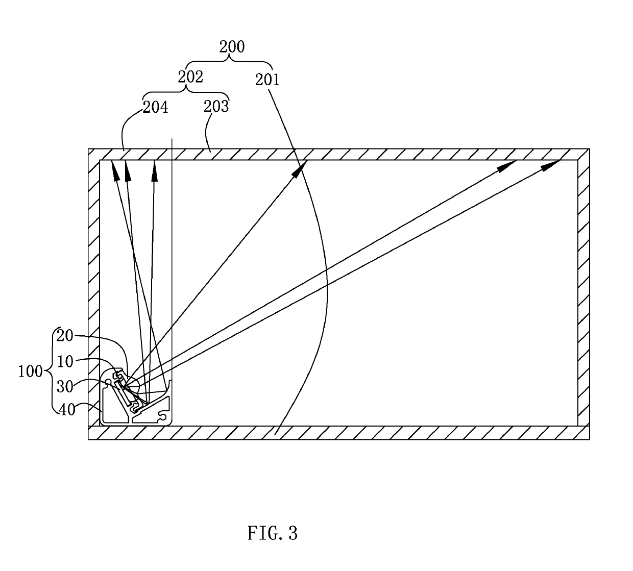
[0023]Please refer to FIG. 1 to FIG. 4, which are schematic structural views and perspective exploded views of a light distribution system for freezer provided by the present invention. The light distribution system for freezer includes at least one LED strip lamp 100, and a freezer 200 for setting the LED strip lamp 100. It is of course conceivable that the light distribution system for the freezer further includes other functional modules, such as a mounting module for mounting the LED strip lamp 100, a power plug module, etc., it shall be a technology learned by technical personnel in the field.

[0024]The freezer 200 should be a well-known household or commercial electrical device for refrigerating or freezing some items such as food, medicin...


PUM


Abstract

A light distribution system for freezer that includes a LED strip light disposed on a freezer door. The LED strip lamp includes a lamp holder, a strip-shaped polarizing lens, and a plurality of LED chips. The lamp holder includes a lens setting surface and a reflecting surface. The strip-shaped polarizing lens includes a plurality of optical axis, an incident surface, a first and second convex lens exit surfaces, and a transition surface. An angle between the illuminated surface and the optical axis includes an acute angle and the illuminated surface includes a main light region illuminated by the outgoing light of the first and second convex lens exit surfaces and a sub-light region illuminated by the reflected light from the reflecting surface.

Description

CROSS-REFERENCE TO A RELATED APPLICATION[0001]This application claims priority to a Chinese Patent Application No. CN 201711210135.0, filed on Nov. 28, 2017.FIELD OF THE TECHNOLOGY[0002]The present invention relates to lighting field, with particular emphasis on a light distribution system for freezer.BACKGROUND[0003]In the context of energy saving and environmental protection, LED lamps are increasingly used in home and commercial lighting because of their high light extraction efficiency and good light collecting performance. Since the LED chip that is once packaged can distribute light in its range of light angles and cannot meet the lighting requirements in most cases, it is generally required to use a lens for secondary light distribution processing. In the field of existing lighting, there is a need to have substantially uniform illumination at both the remote and near illumination. When the general light source is irradiated at different distances, because the far-illuminated...

Claims


Application Information

Patent Timeline
Patent Type & Authority Applications(United States)
IPC IPC(8): F21V33/00F21V5/04F21V7/00F21V13/04F25D27/00
CPCF21V33/0044F21V5/04F21V7/005F21V13/04F25D27/00F21Y2103/10F21Y2115/10F21S8/00F21V19/001F21V23/00A47F3/04F21S4/20F21V7/04F21V9/14F21W2131/305F21S4/28F21V5/043F21V5/08F21V7/0008
Inventor JI, FENGZHENG, ZHAOYONGXU, BOZHANG
Owner SELF ELECTRONICS CO LTD
Why Eureka
Try Eureka