Projection tube having different neck diameters

a technology of projection tube and neck diameter, which is applied in the direction of cathode ray tube/electron beam tube, electric discharge tube, tube with screen, etc., can solve the problems of deterioration of focusing performance, cathode ray tube has not been commercialized, and cathode ray tube has not been also commercialized, so as to prevent the distance

Inactive Publication Date: 2005-01-25
HITACHI LTD +1
View PDF18 Cites 3 Cited by
  • Summary
  • Abstract
  • Description
  • Claims
  • Application Information

AI Technical Summary

Benefits of technology

In the electron gun of the present invention, to prevent the distance between a phosphor screen and a main lens of the electron gun from becoming large, a final electrode of the electron gun is constituted of a large-diameter cylindrical portion, a small-diameter portion and a portion which gradually decreases a diameter thereof, the large-diameter portion of the final electrode is mounted in a large-diameter portion of a neck and the small-diameter portion of the final electrode is provided to a small-diameter portion of the neck.

Problems solved by technology

However, such a cathode ray tube has not been commercialized yet.
Accordingly, the total length of the cathode ray tube is elongated and hence, it gives rise to disadvantages such as the deterioration of the focusing performance as side effects.
However, such a cathode ray tube has not been also commercialized yet.
Accordingly, it is difficult to take a large shrinkage rate of the neck diameter and hence, the deflection sensitivity enhancing effect becomes extremely small.

Method used


Image

  • Projection tube having different neck diameters
  • Projection tube having different neck diameters
  • Projection tube having different neck diameters

Examples


first embodiment

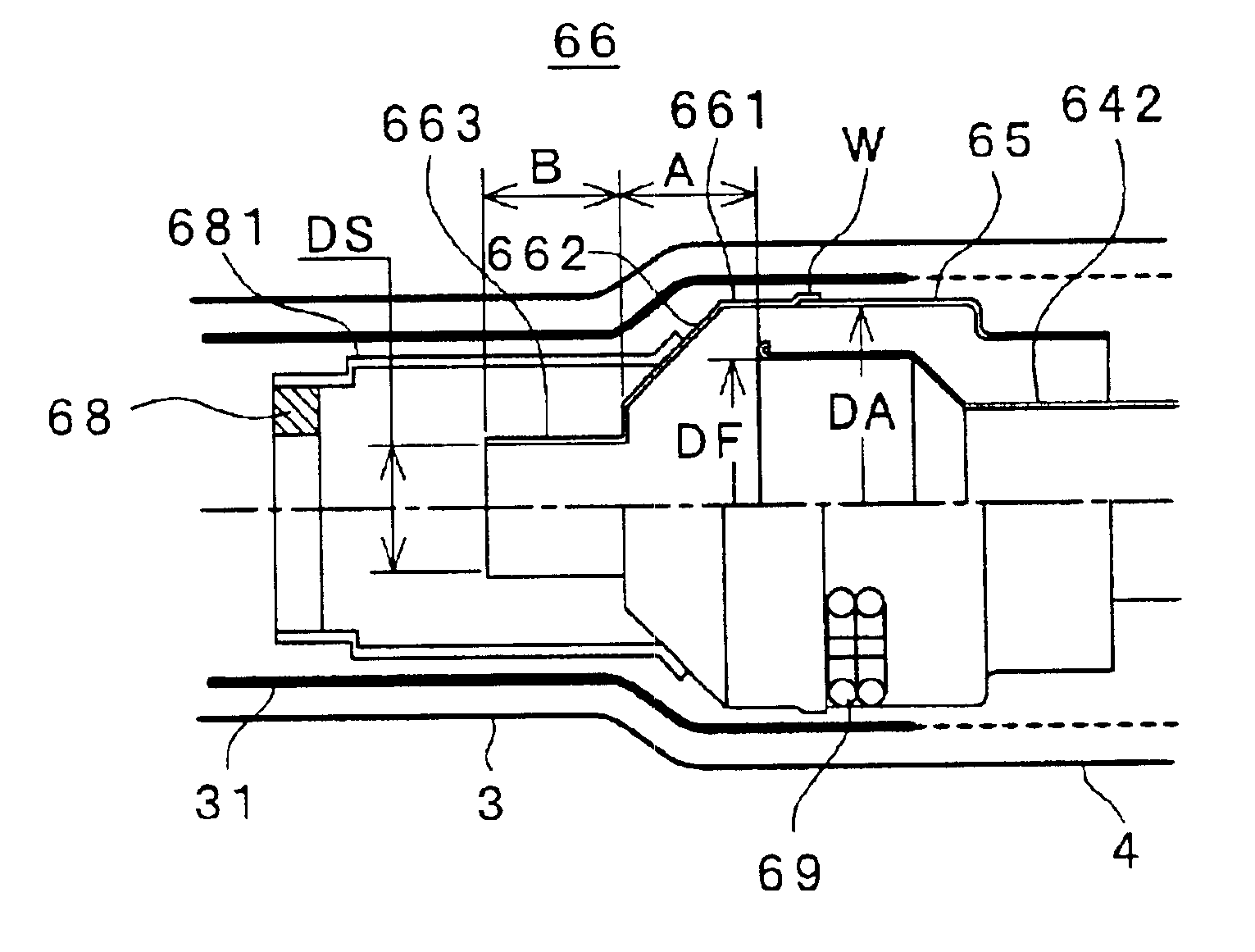
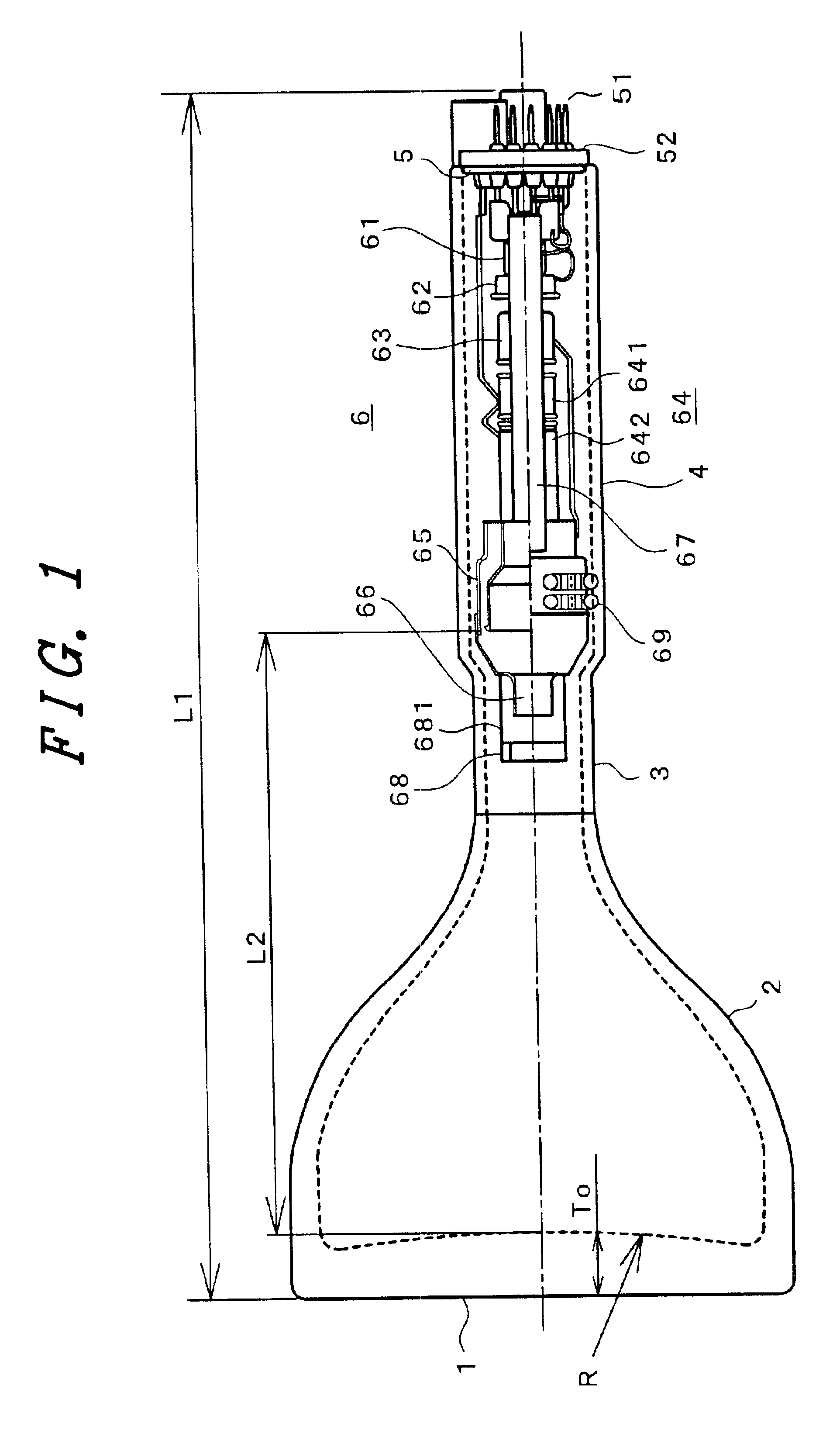
FIG. 2 is a detailed view of the electron gun in the vicinity of the main lens. The second anode 65 and the shield cup 66 overlap each other at a portion W thus forming a final electrode. An inner diameter DA of the second anode 65 is set to 27.8 mm which is substantially equal to the inner diameter of a large-diameter portion 661 of the shield cup 66. The focus electrode 642 enters the inside of the second anode 65 thus forming a large-diameter electron lens. An inner diameter DF of a distal end portion of the focus electrode 642 is set to 20.5 mm.

In this embodiment, the main lens is substantially formed of the large-diameter portion 661 of the shield cup 66 and the focus electrode 642. An inner diameter DS of a small-diameter portion 663 of the shield cup 66 is set to 9 mm. This provision is provided to prevent the deterioration of the withstand voltage which occurs due to the adhesion of the getter 68 to the focus electrode 642 or the like by a backlash when the getter 68 is scat...

second embodiment

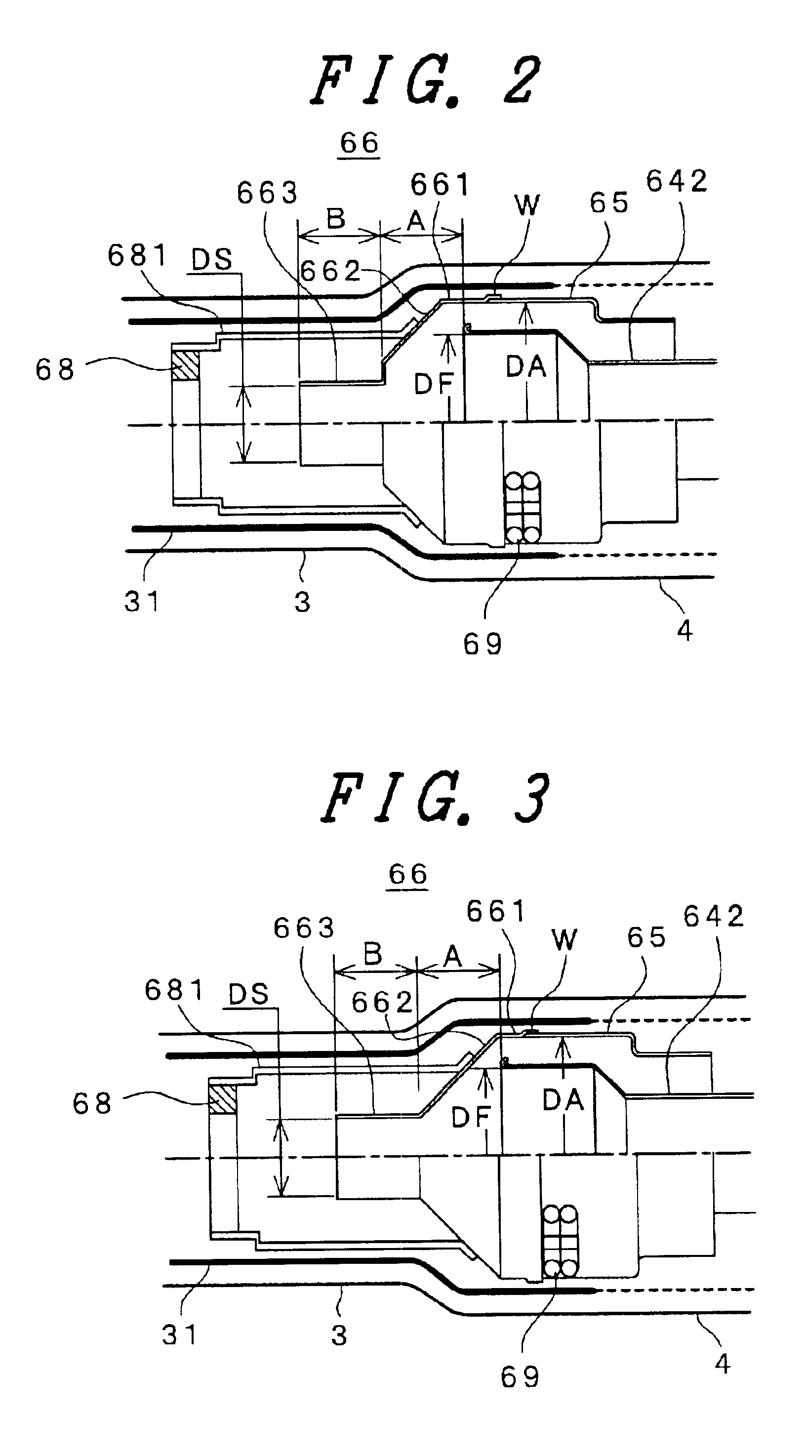
FIG. 3 shows the electron gun in the vicinity of the main lens. The constitution shown in FIG. 3 differs from the constitution of FIG. 2 in that a transition portion 662 from the large-diameter portion 661 to the small-diameter portion 663 of the shield cup 66 is not stepped but is formed in a straight line. This embodiment is characterized in that the electron gun can be positioned closer to the phosphor screen side by an amount obtained by forming the straight transition portion 662.

FIG. 4 shows a third embodiment of the electron gun in the vicinity of the main lens. In the third embodiment, the bulb spacer contact 69 is mounted on the small-diameter portion 663 of the shield cup 66 and is brought into contact with an inner wall of the small-diameter portion 3 of the neck. In this case, it is sufficient to coat the neck graphite 31 only onto the inner wall of the small-diameter portion 3 of the neck. The productivity and the reliability can be enhanced by an amount obtained by mak...


PUM


Abstract

The present invention aims at maintaining the high focusing performance with a low deflection power in a projection tube which is used as a projection type TV receiver or a projector and is operated at a high voltage and with a single-electron-beam high current. A neck outer diameter of a portion on which a deflection yoke is mounted is made smaller than a neck outer diameter of a portion which accommodates an electron gun. A final electrode of the electron gun has a diameter thereof gradually decreased toward a phosphor screen. The maximum anode voltage of the projection tube is set to equal to or more than 25 KV and the maximum beam current is set to equal to or more than 4 mA.

Description

BACKGROUND OF THE INVENTION1. Field of the InventionThe present invention relates to a projection tube which is used in a projection type TV receiver, a video projector or the like.2. Description of the Related ArtAn image of a cathode ray tube can be obtained by scanning an electron beam emitted from an electron gun by means of a deflection yoke. The deflection yoke is mounted in the vicinity of a joint portion between a neck and a funnel. The deflection sensitivity is enhanced as the neck outer diameter becomes smaller. However, when the neck outer diameter is made small to enhance the deflection sensitivity, the electron gun which is accommodated in the neck portion must be miniaturized correspondingly. When the electron gun is miniaturized, the diameter of an electron lens becomes small and hence, the focusing is degraded. That is, the deflection sensitivity and the focusing performance are in an opposed relationship.A method which can solve such a problem is, for example, propo...

Claims


Application Information

Patent Timeline
Patent Type & Authority Patents(United States)
IPC IPC(8): H01J29/48H01J29/86H01J31/12H01J31/10
CPCH01J29/485H01J29/861H01J2229/8603H01J31/12
Inventor SUZUKI, NOBUYUKIAOKI, KOTAROSAITOU, KOUICHISHIRAI, SHOJI
Owner HITACHI LTD
Why Eureka
Try Eureka