Operation of an electromagnetic radiation focusing element

a technology of electromagnetic radiation and focusing element, which is applied in the direction of optical radiation measurement, instruments, spectrometry/spectrophotometry/monochromators, etc., can solve the problems of reducing the effect of diffraction, increasing the effect of aberration, and affecting so as to improve the performance improve the operation of the focusing element.

Active Publication Date: 2013-06-27
J A WOOLLAM CO
View PDF1 Cites 4 Cited by
  • Summary
  • Abstract
  • Description
  • Claims
  • Application Information

AI Technical Summary

Benefits of technology

[0026]The present invention is a system for improving the operation of a focusing element as a function of wavelength, to improve the performance of the focusing element. Said system comprises, in either order:

Problems solved by technology

It is known that focusing element, such as refractive lenses and lens systems, cause both diffraction and aberration to occur in a beam of electromagnetic radiation with which is interacts.
That is, as the beam cross-sectional area is increased, the effects of diffraction decrease, but the effects of aberration increase.
That is, there exists a cross-section area such that increase or decrease in cross-sectional area will cause combined diffraction or aberration to become worse, (ie. cause lens performance to be worse).
Said two laser beams, however, are elliptical in cross-sectional shape as they exit the sources thereof, which is not optimum for us in CD-DVD systems.
However, Kibabayashi 501 does not remotely suggest this at all, as it does not even mention correcting for diffraction of a beam.

Method used


Image

  • Operation of an electromagnetic radiation focusing element
  • Operation of an electromagnetic radiation focusing element
  • Operation of an electromagnetic radiation focusing element

Examples


Embodiment Construction

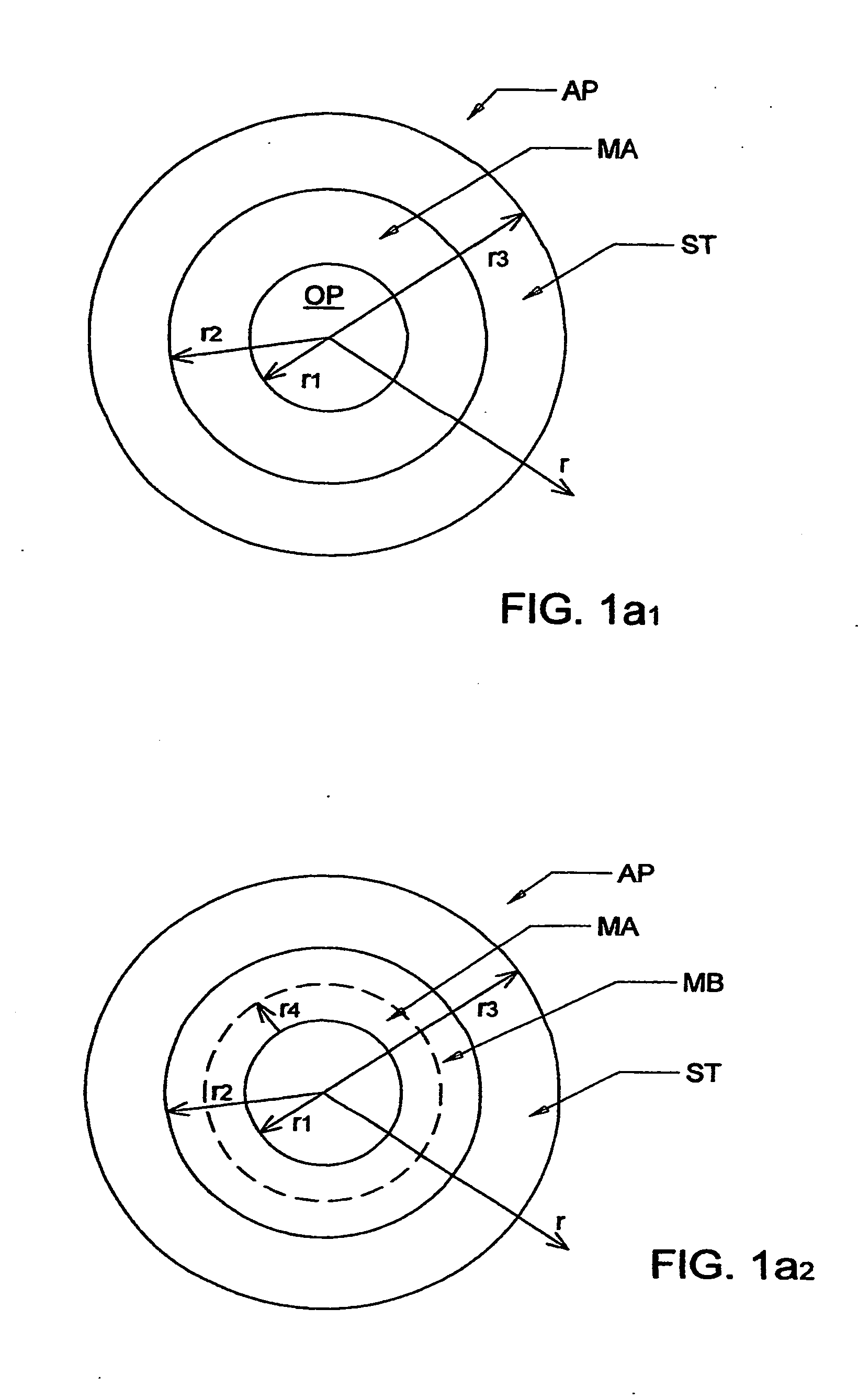
[0104]Turning now to the Drawings, FIG. 1a1 shows an aperture (AP) which is made from various materials at various radial (r) extents. Radius (r1) identifies a opening through which a electromagnetic radiation of a given wavelength can pass. Radius (r2) shows a region of the aperture, outside the radius (r1), which is made of material (A), and radius (r3) shows a region beyond radius (r2) which is a beam stopper (ST). FIG. 1a2 also shows that the aperture (AP) can comprise additional areas made of various other materials, (eg. (MB) between r1 and r4). Additional concentric rings of different materials can be present and the Drawings are to be considered demonstrative and not limiting. A similar plot results for each wavelength. Further, note that the material present between indicated radii r1 and r2 is the same through said 360 degrees, as is the different material between radii r2 and r4. Support for this is found in the present Application FIGS. 1a1 and 1a2. It is noted that this...


PUM


Abstract

A combination of a focusing element, and a filtering element which naturally adjusts the cross-sectional area of a beam of electromagnetic radiation passed through the focusing element as a function of wavelength, optionally as an element of an ellipsometer or polarimeter system.

Description

[0001]This application is a CIP of application Ser. No. 12 / 661,974 Filed Mar. 25, 2010, and therevia Claims Benefit of 61 / 211,055 filed Mar. 26, 2009.TECHNICAL FIELD[0002]The present invention relates to a system of aperturing a focusing element by use of a filtering element to arrive at an optimum electromagnetic beam cross-sectional area passed by the filtering element, based on optimizing said cross-sectional area in view of conflicting effects of aberration and diffraction inherent in said focusing element, which, for each wavelength, vary oppositely to one another with electromagnetic beam cross-sectional area. More particularly the present invention is a combination of a focusing element, and a filtering element which improves the operation of the focusing element as a function of wavelength in a beam of electromagnetic radaition.BACKGROUND[0003]It is known that focusing element, such as refractive lenses and lens systems, cause both diffraction and aberration to occur in a be...

Claims


Application Information

Patent Timeline
Patent Type & Authority Applications(United States)
IPC IPC(8): G02B3/00
CPCG02B3/00G02B5/005G02B27/46G02B27/58G01J3/0229G01J4/00G01J3/0208
Inventor LIPHARDT, MARTIN M.
Owner J A WOOLLAM CO
Why Eureka
Try Eureka