Eureka AIR delivers breakthrough ideas for toughest innovation challenges, trusted by R&D personnel around the world.

Cautery apparatus

Pending Publication Date: 2019-08-01
TYCO HEALTHCARE GRP LP
View PDF3 Cites 0 Cited by
  • Summary
  • Abstract
  • Description
  • Claims
  • Application Information

AI Technical Summary

Benefits of technology

The patent describes a cautery device which includes a handpiece and a cautery tip. The tip has a channel that extends from the handpiece to the distal end, and is connected to a gas supply and an electric supply. The device also has a multilumen tube that includes a gas lumen and an electrical conductor lumen. The gas and electricity are introduced to the cautery tip through the gas lumen and the electrical conductor, respectively. The device also has a switch that can regulate the supply of electricity to the cautery tip based on the position of the handpiece. The technical effects of the invention include the efficient delivery of gas and electricity to the cautery tip, and the regulation of the supply of electricity based on the position of the handpiece.

Problems solved by technology

The use of cautery devices on tissue results in the generation of smoke and vapor, which are unwanted byproducts that reduce visibility in the area of the tip.
Also, cautery devices have the potential to provide enough energy to cause fires in an operating room environment, which is typically a high oxygen environment.

Method used


Image

  • Cautery apparatus
  • Cautery apparatus
  • Cautery apparatus

Examples


Embodiment Construction

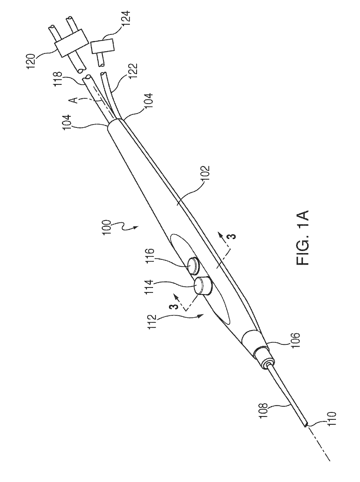
[0017]FIG. 1A shows an embodiment of a cautery device 100 that includes an elongated housing 102 that extends longitudinally along an axis A-A from a proximal end 104 to a distal end 106. The device 100 also includes a removable hollow cautery tip 108 that extends longitudinally from the housing coaxially with axis A-A. The cautery tip 108 defines an open channel 110 that extends axially completely through the tip 108. The open channel 110 is preferably coaxial with the axis A-A. The housing 102 defines a handpiece 112 that is arranged so that it may be grasped in a user's hand like a writing instrument to direct the cautery tip 108 during a surgical procedure while also allowing a user of the device 100 to actuate buttons 114, 116 that extend from the housing 102. As will be described in greater detail below, the cautery tip 108 receives electric power to operate the tip 108 so that it can be used to perform various cautery tool procedures, such as cutting and coagulation. Also, th...


PUM


Abstract

A cautery device includes an elongated handpiece and a cautery tip extending from the handpiece. The tip defines a channel extending coaxially with the handpiece along an entire length of the cautery tip from a proximal open end to a distal open end. The device includes a gas supply connection extending from the proximal end of the handpiece for supplying gas to the cautery tip. The gas supply connection is fluidly coupled to the cautery tip. The device includes an electric supply connection extending from the proximal end of the handpiece for supplying electricity to the cautery tip. The electric supply connection is electrically coupled to the cautery tip. The gas supplied to the cautery tip is introduced to the channel at the proximal open end and exits the tip at the distal open end.

Description

CROSS-REFERENCE TO RELATED APPLICATIONS[0001]This application is a continuation of U.S. patent application Ser. No. 14 / 615,763, filed on Feb. 6, 2015, which claims the benefit of the filing date of provisional U.S. Application No. 62 / 075,897, filed on Nov. 6, 2014, the entire contents of each of which are incorporated herein by reference.INTRODUCTION[0002]The present invention relates to surgical instruments, and more particularly a cautery apparatus.BACKGROUND[0003]Cautery devices have been used in surgical procedures to perform cutting and coagulation of tissue and blood vessels. Typically, cautery devices are “pen”-like devices that a surgeon can grasp by the hand to use. The cautery device typically is connected to an electrical generator that outputs a level of current that is conducted to a tip of the device to achieve the desired cutting and / or coagulation effect during a surgical procedure.[0004]The use of cautery devices on tissue results in the generation of smoke and vapo...

Claims


Application Information

Patent Timeline
IPC IPC(8): A61B18/08
CPCA61B18/082A61B2218/005A61B2018/00958A61B2018/00595A61B2018/00589A61B2018/048A61B2018/00922
Inventor TRIVEDI, AMITCAMPANELLI, THOMAS J.PEDROS, ROBERTO
Owner TYCO HEALTHCARE GRP LP
Why Eureka
Eureka Blog
Learn More