Coupler betwen a coaxial connector and a coaxial cable

Active Publication Date: 2019-08-15
ROSENBERGER HOCHFREQUENZTECHNIK GMBH & CO KG
View PDF6 Cites 0 Cited by
  • Summary
  • Abstract
  • Description
  • Claims
  • Application Information

AI Technical Summary

Benefits of technology

[0024]An annular component is preferably to be inserted between the radial extensions of the first and the third sleeve-type component of the locking device. The coefficient of sliding friction of the annular component is less than a previously defined threshold value. In this way, a

Problems solved by technology

Disadvantageously, therefore, the distance between the two clamping surfaces, and the clamping force acting between the two clamping surfaces upon the clamped-in outer conductor braid, are not reproducible.
In addition, owing to the resp

Method used


Image

  • Coupler betwen a coaxial connector and a coaxial cable
  • Coupler betwen a coaxial connector and a coaxial cable
  • Coupler betwen a coaxial connector and a coaxial cable

Examples


Example

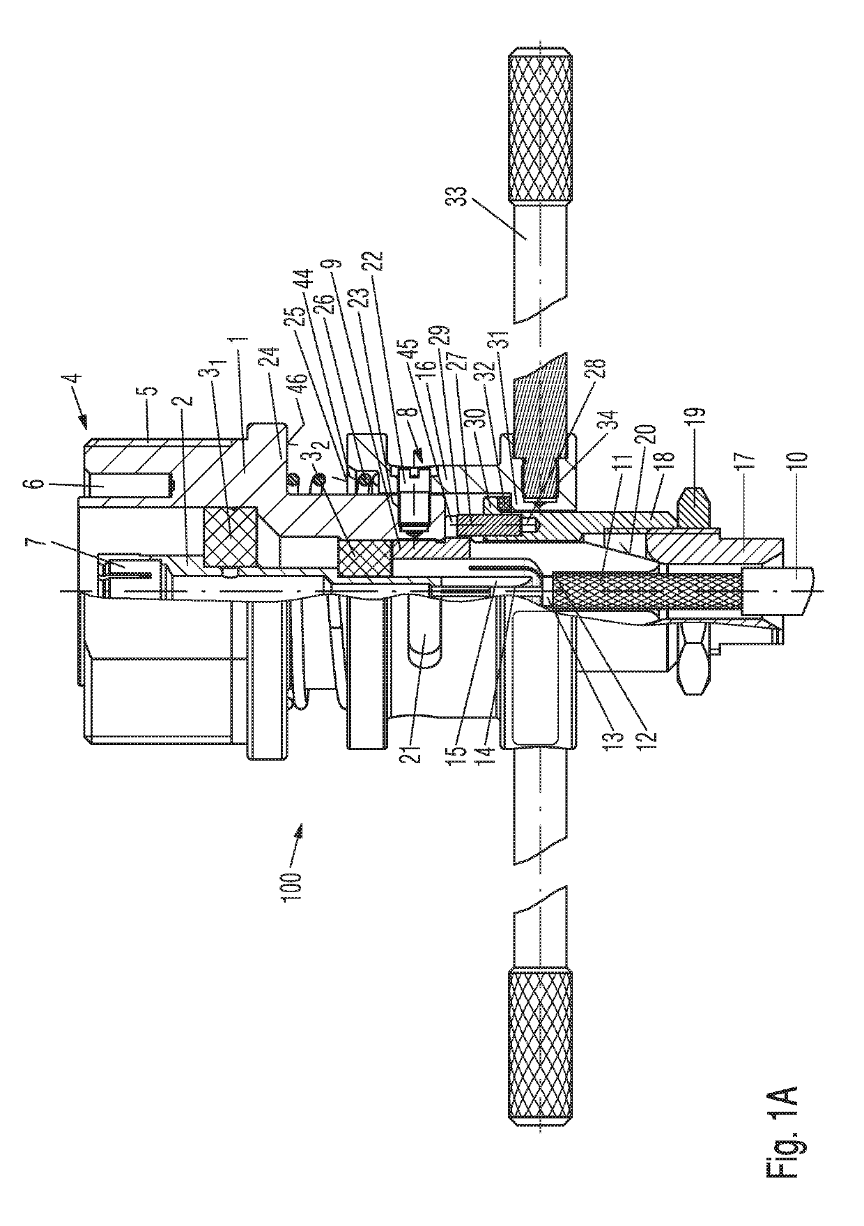
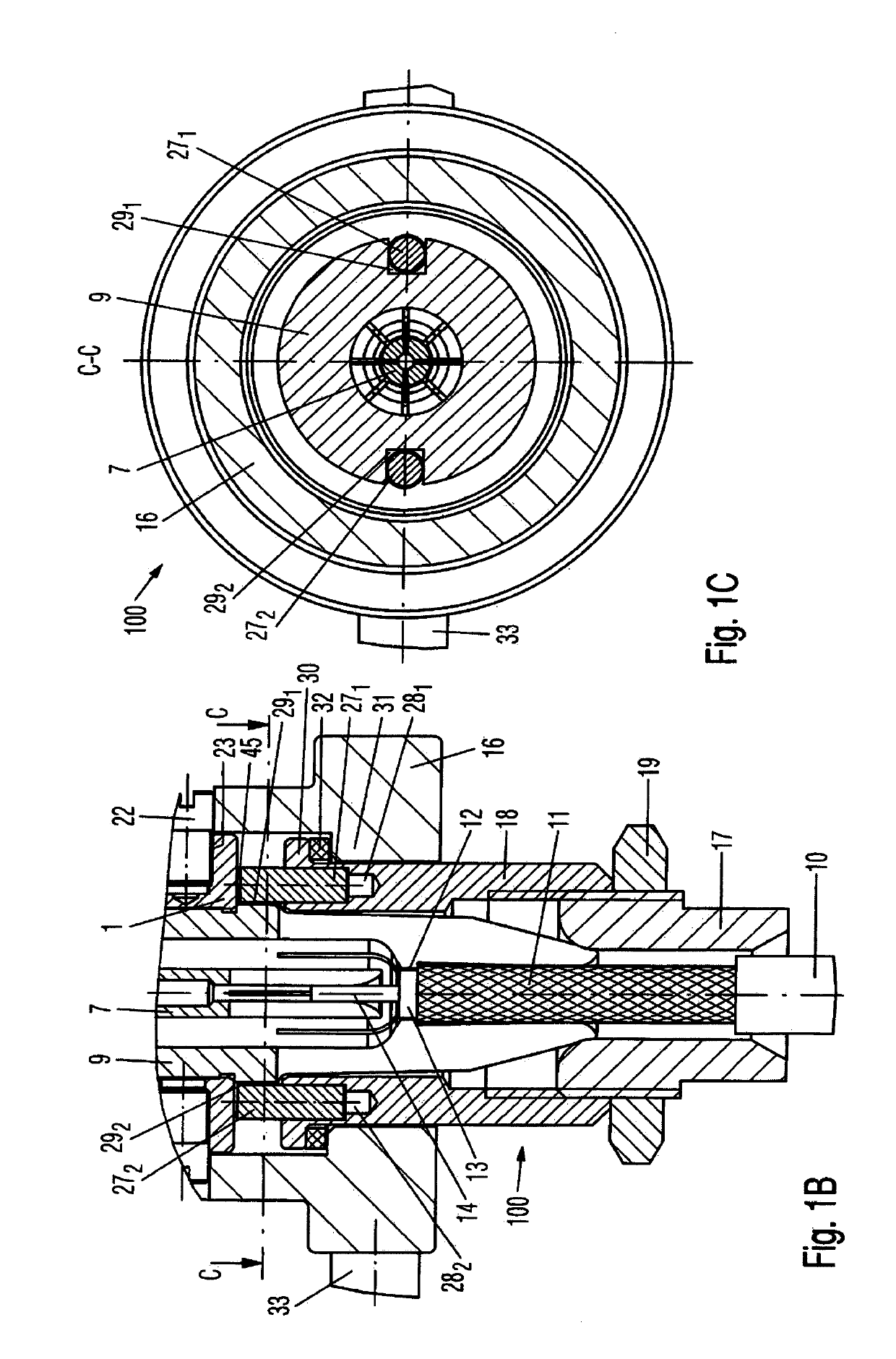
[0033]The first embodiment 100 of the coupler in accordance with the invention is described in detail in the following on the basis of FIGS. 1A, 1B and 1C:

[0034]The coupler 100 has a first coaxial connector, which is constructed according to a coaxial plug-and-socket connector standard suitable for high-frequency signals, for example according to the Threaded Neill-Concelman (TNC) standard.

[0035]This first coaxial connector comprises a substantially hollow cylindrical outer conductor 1, an inner conductor 2, which is arranged so as to be coaxial with the outer conductor 1 and which is substantially cylindrical, and at least one insulator part 31 and 32, which adjoins, respectively, the inner cylindrical surface of the outer conductor 1 and the outer cylindrical surface of the inner conductor 2, and which is substantially in the form of a hollow cylinder.

[0036]Instead of two insulator parts 31 and 32, there may also be provided a single insulator part, which fills the entire space be...

Example

[0070]FIGS. 2A and 2B show a second embodiment 100′ of the coupler, wherein the same references denote parts that are functionally the same as in FIGS. 1A, 1B and 1C, in which a first embodiment 100 of the coupler is represented in each case, such that reference is made to the above description of FIGS. 1A, 1B and 1C for explanation of these parts.

[0071]In the second embodiment 100′ of the coupler, the bayonet connection between the outer conductor 1 of the first coaxial connector and the first sleeve-type component 16 of the locking device is realized in that at least one guide pin 22 is fastened in an associated bore 35 in the first sleeve-type component 16 of the locking device, and is guided in an associated elongate bore 36 in the outer conductor 1 of the first coaxial connector. The fastening of each guide pin 22 in the associated bore 35 in the first sleeve-type component 16 is preferably effected by a screwed connection. Preferably also provided in the second embodiment 100′...


PUM


Abstract

A coupler (100; 100′) between a first coaxial connector and a coaxial cable (10) has a first coaxial connector with an inner conductor (2), at least one hollow cylindrical insulator part (27; 271, 272) and a hollow cylindrical outer conductor (1) and a first spring sleeve (9) for accommodating an outer conductor (11) of the coaxial cable (10), which spring sleeve is connected to the outer conductor (1) of the first coaxial connector. In addition, the coupler (100; 100′) in accordance with the invention has a locking device, which is axially movable relative to a longitudinal axis of the first coaxial connector and is supported on a conically realized outer surface (20) at a distal end of the first spring sleeve (9). The outer conductor (1) of the first coaxial connector is connected to the locking device via a bayonet connection.

Description

FIELD OF THE INVENTION[0001]The invention relates to a coupler between a coaxial connector and a coaxial cable.BACKGROUND OF THE INVENTION[0002]In the testing of coaxial cables, leakage parameters of the coaxial cable are typically measured by means of a vectorial network analyzer. Other important characteristics of the coaxial cable such as, for example, the standing wave ratio, or intermodulations occurring in the coaxial cable, are determined from the measured leakage parameters.[0003]The test system also comprises, besides the vectorial network analyzer, a high-frequency measurement cable, a coupler and the coaxial cable to be tested. The high-frequency measurement cable is connected, on the one hand, to an interface of the vectorial network analyzer, and on the other hand to a coaxial connector. This coaxial connector, in the following referred to as a second coaxial connector, together with a further coaxial connector, which belongs to the coupler and which in the following is...

Claims


Application Information

Patent Timeline
IPC IPC(8): H01R9/05H01R13/625
CPCH01R9/05H01R13/625H01R4/54H01R9/0524H01R9/0518H01R9/0521H01R13/622H01R24/38
Inventor FANG, RONGPETERANDERL, JOSEFKRAUTENBACHER, SABINE
Owner ROSENBERGER HOCHFREQUENZTECHNIK GMBH & CO KG
Why Eureka
Try Eureka